SP-4206 Stages to Saturn
[235] During World War II, the growing sophistication of weapon systems and communications equipment prompted development of test procedures to ensure that everything was in proper working order. Automatic testing, or checkout, saved time and reduced the large number of specialists who would otherwise have to be trained to do the job. In the post-World War II era, larger and ever more complex missile systems created new difficulties in testing and monitoring the internal condition of the missile. Computers were introduced not only to measure the level of fuel and oxidizer in the tanks, but also to assess propellant qualities such as temperature, stratification, and boil-off rates. Continuous monitoring of the condition of propellant machinery, missile electronics, and various internal rocket systems became significant functions of computer check-out. The Atlas, the first American ICBM, used the kind of comprehensive checkout equipment that would be elaborated in the course of the Apollo-Saturn program. Once launched, rockets like the Atlas needed precise guidance and control. Other, smaller computers and associated equipment aboard the vehicle maintained the proper course and controlled the flow of propellants. Again, the Apollo-Saturn elaborated on equipment developed for ICBMs.1
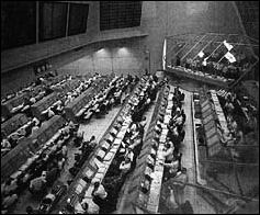
"A check-out system is considered automatic" according to one definition, "when it can, to some degree, autonomously sequence a series [236] of measurements of equipment outputs and comparisons of these measurements against standards." A manual test system, on the other hand, required the operator to switch the equipment from one reading to a different one and to make comparisons on "go/no-go" conditions. For NASA engineers, the intricacy and enormity of measurement and comparison was evident by taking a look at the number of comparison test points in the Apollo-Saturn vehicle. Vanguard, produced by Martin, required only about 600 test points. The Apollo spacecraft, on the other hand, included over 2500 test points on the command module and the lunar module, and another 5000 on the Saturn itself. Further, these test points were checked and monitored constantly from early manufacturing checkout sequences, to pre-static-firing checkout, to post-static-firing checkout. Test points were checked scores of times in the 12-14 weeks required prior to a launch for complete checkout of the Apollo-Saturn stack at Cape Kennedy. Without computer technology, such procedures, even at the launch site, might have stretched out the checkout procedures for more than a year.2 Checkout equipment and procedures went beyond the point of merely pinpointing a fault in the equipment. The automaticd checkout paraphernalia associated with the Apollo-Saturn program additionally incorporated a diagnosis function; computer or screen readouts would indicate to the test engineers and programmers not only that a problem existed, but also the nature of the problem, its causes, and possible solutions.3
In the evolution of automaticd checkout equipment, one of the most interesting problems centered on the creation of a new language. The language tapes incorporated in the computer programs had to be functional for the designer of the vehicle as well as the test engineer. Readouts on malfunctions had to make sense to persons reworking the piece of hardware that failed or had not performed properly. Obviously,....
[237] ....each of these individuals came to the language problem from a different background and with a different goal in mind. Melding two such disciplines together was not always an easy task. Earlier in the Saturn program, Marshall Space Flight Center had developed two separate languages for computer operations-one for stage testing and one for launch site operations. This situation obviously created communications problems and was complicated by the fact that each of the stage manufacturers was also using its own computer language based on the particular requirements of its own test designers and engineers. A further entanglement involved the rapid evolution of checkout programs. Test engineers were putting new demands on the computers, and these new demands as well as the style of language had to be communicated to the programmer. To arrive at an appropriate language, either the test engineer had to learn more about programming, or the programmer had to learn more about test engineering. The solution to this dilemma was ATOLL, an acronym for Acceptance Test or Launch Language, designed to bridge many of the gaps between the test engineer, the designer of the stage, and the computer programmer. Originating in late 1963, ATOLL eased confusion and helped to normalize the many functions of automatic test and checkout encountered at the manufacturer's plant, during static firing, and during operations at the launch site.4
In a typical test sequence a number of things happened. For example, the test engineer inaugurated the program by typing in the instructions on his console. The computer responded by reading out for the test engineer the status of the selected program. When the program was ready for running, this was indicated on the appropriate panel of the computer. The information appeared in English on either the cathode tube of the program display or on a video data terminal. Perhaps the display also included numerous options for the engineer, depending on which portions of the test he wanted to pursue at the time. If some selected part of the test required a further breakdown for the engineer's consideration, instructions could also be typed in, and the computer would respond on the display tube. When either programming difficulties or hardware problems cropped up, the computer might give the test engineer a choice of several actions: terminate the test, go back to a prior enumerated step, proceed, or some other option. Further, in the process of running the test, all the results were shown on engineering display consoles and recorded both in print and on magnetic tape. These readouts were stored and, in some instances, were correlated into previous test operations for checking at some later date. Thereafter, if an anomaly occurred, it was possible to run a check through the computer all the way back to the machine shop floor to see what discrepancies or difficulties might have occurred in the test conditions, hardware, or in the manufacturing process itself.5
[238] Prior to the static-firing program (and before any mating of the separate stages occurred), each Saturn stage had to pass checkout requirements. Although the final test goals were similar for each stage, the differences between stages required a "custom-tailored" test for each one. Designing a checkout system to satisfy the unique requirements of the instrument unit and each stage, and also meet integrated vehicle requirements, became what MSFC called a "major task." The Marshall group drew on its experience with the Redstone, Jupiter, Mercury, Saturn I, and other rocket programs in establishing the checkout organization.6
The decision to use automaticd stage checkout for the Saturn program rested on several factors. D.M. Schmidt, of MSFC's Quality and Reliability Assurance Laboratory, summarized them at a technical conference in New York City in 1965:
- High reliability is needed; vehicle is expensive and is man-rated.
- Truly integrated designs of stages and support equipment would reduce the number of operational problems.
- Human errors and human slowness must be improved upon.
- An engineering approach is feasible throughout design, production and test, military restraints being absent.
- The time scheduled for checkout must be used more effectively than on previous programs.
- The volume of technical data to be measured and handled is extremely large; each flight stage alone has hundreds of measuring devices aboard (perhaps as high as 1000).
- All data must be transmitted long distances on a limited number of channels. Launch pads are far from control consoles. Stage checkout must meet launch needs.
- Test and launch data must be retrieved, stored, and made available to many organizations.
- Automation increases the powers of human operators to deal with complex situations and frees them for decision-making.
- Data-handling needs are many and varied: accuracy of measurements and transmission, versatility of equipment, speed of operation, operating-time recording, failure histories, data comparisons.7
For the Saturn program, checkout included two distinct phases. "Stage checkout" included test sequences conducted on the individual stage during manufacturing and static firing prior to NASA's acceptance for assembly into the launch vehicle. "Vehicle checkout" included tests on the assembled launch vehicle at the launch site. A complete checkout of the stack was deemed necessary because an individual stage might function perfectly in tests that simulated interaction with other stages, but not function as well when linked together physically in the stack. [239] Marshall's main interest was the actual stage checkout, with responsibility for final launch vehicle checkout resting with Kennedy Space Center. Originally, NASA planners envisioned repeating the stage checkout after the delivery of each stage to Cape Kennedy, but it became apparent that this scheme compromised the time and resources required for final checkout and launch. Therefore each stage received final checkout before transport to the launch site. The procedure not only made it easier to accomplish the final checkout and launch, but enabled MSFC and the contractors to deal more efficiently with problem areas at the stage test facility (where specialized personnel and equipment were present). This concept paid off on the first three Saturn V vehicles when stage checkouts uncovered 40 serious defects; these flaws would have gone undetected had the stage checkout depended only on procedures and facilities available at the launch site.8
Each booster stage was subjected to a post-manufacturing checkout, a checkout prior to static-firing tests, and a post-static-firing checkout. Static firing, the most dramatic test, tested the propulsion systems during actual ignition and operation. Checkout featured a "building-block" sequence, common to all stages, with variations as necessary for an individual stage. A typical sequence began with an independent electrical system test and was followed by a simplified rundown of the launch sequence. Next, other systems were run in succession; guidance and control system tests; a second launch sequence run with these and other electrical and propulsion systems tested; completion of ancillary system tests; an all-systems test; and, finally, a "simulated flight" test, including ignition and a duration burn.9
The Saturn stages and the associated checkout equipment for each were developed simultaneously with the goal of an integrated design of the vehicle and its ground equipment. Some of the vehicle's mechanical equipment-such as sensing equipment for checkout of a number of items operated by fluid, as well as fluid management subsystems-did not lend themselves to checkout with digital computers. Design engineers succeeded in developing suitable checkout equipment for the electrically actuated and measured equipment so that the great majority of stage checkout tests would proceed automatically. The Saturn I vehicles offered the first experiences in stage checkout for Saturn class vehicles. Whereas the vehicle SA-1 required manual checkout, by the end of the Saturn series automatic equipment controlled over 50 percent of the tests. The automatic capability improved during the S-IB vehicle series, ad checkout of the Saturn V stages, including the instrument unit (IU), was about 90 percent automaticd.10
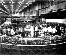
Checkout equipment for S-II and S-IVB stages of the Saturn V was developed by the stage contractors under the direction of MSFC. For the S-IC, Marshall collaborated with Boeing in developing the automaticd equipment, because the first S-IC stages were fabricated in MSFC shops [240] at Huntsville. Boeing employees trained on the first two S-IC stages at Huntsville, then checked out later stages at Michoud. For the IU, checkout equipment previously developed by Marshall for the Saturn I was utilized, with IBM in Huntsville assuming responsibility for later work. The S-IC stage and the IU checkout operations both utilized the RCA-110A digital computer. NASA had already decided to use the RCA-110A for launch control, so the interfaces with the S-IC and IU were compatible. In contrast, the S-II and S-IVB stages relied on the CDC-924A computer, supplied by Control Data Corporation. The design of the computer offered added flexibility for checkout of the two upper stages, which utilized liquid hydrogen as fuel, mounted the J-2 engine, ignited at high altitude, and included several unique design features. Also the CDC-924A, which was based on later-generation computer technology, offered added test functions.11 The Saturn program also relied heavily on the "Saturn V Systems Breadboard," a facility located at MSFC. The breadboard incorporated both mechanical equipment and electronic simulation and was used for wringing out the checkout procedures and launch control operations at the Cape.12
Not everyone was happy about the escalating preeminence of automation. Many of Douglas's own people opposed the ubiquitous computer. "In fact," an automation expert at Douglas admitted, "the company was surprised to find that its equipment took the automation more readily than did its engineers."13
In the pre-Saturn days of rocket and missile operations, many checkout procedures were performed manually and worked well with complex vehicles like the Thor-Delta. Douglas engineers used manual checkout techniques for the earliest S-IV stages; pre-checkout, acceptance firing, and post-checkout required a total of 1200 hours per stage. Veteran "switch flippers," who for so long scanned gauges and dials, flipping the right switch in a critical situation, had been vital links in the overall loop. They were now replaced by ranks of gray-enameled computers. For checkout procedures on the Saturn V third stage, the S-IVB, fully automaticd techniques replaced the manual checkout for the first time. Although the magnitude of testing rose by 40 percent per stage, the new automaticd systems reduced the checkout time to about 500 hours total. H. E. Bauer clearly remembered the occasion when men and the new machines first confronted each other. "One seasoned switch flipper came into the blockhouse after the equipment was installed; he watched the blinking lights, the scanners, the recorders- everything was working automatically, heaving out wide and endless runs of data printouts...." The man balefully surveyed the mechanically throbbing interloper and growled. "It's the Gray Puke!" It was not an isolated reaction. As Bauer recalls, the ghastly name stuck and became part of the permanent lexicon associated with the S-IVB stage.
Even with mechanical drones like the Gray Puke usurping the [241] human role, the man-behind-the-machine could still display some semblance of individuality. Consider, for example, the case of the petulant computer-printer-when the machine apparently took umbrage during the automatic checkout sequence in preparation for an acceptance firing. The moment of truth for the test arrived-the signal to fire. After uncounted hours of preparation, hundreds of workers now stood by to observe the climactic moment of ignition. In the crowded blockhouse, all eyes focused on the rows of computers and monitor screens displaying their last fragments of information. Finally, the test conductor typed in his "request" to start the terminal countdown for static firing. The computer whirred, and the automatic typewriter responded with a singular reply, "Say please." Startled, the test conductor concluded he had made a typing error, and repeated his original message more carefully. The balky computer was not to be denied. "Say please," it insisted. At this point the crowd in the blockhouse began stirring restlessly. The loaded S-IVB, readied for firing, remained poised nearby with thousands of gallons of liquid oxygen and liquid hydrogen primed for detonation. People were getting tense. Reasonably certain he was only working against a faulty firing tape, the test conductor quickly decided to make one more try, rather than put it into discard and risk more precious time to put a replacement tape into operation. So once more, he entered into the machine his humble request to fire, with a polite notation at the end: "please." This time, there was no problem. "This is your programmer," the machine chattered back, "wishing you good luck." And with a roar, the rocket ignited.14
With computer data accumulated for each stage and subsystem, the collected information was not only utilized for vehicle checkout at the Cape, but also for the launch and for guidance and control during the mission.
After years of research and development on the individual stages, involving thousands of workers and millions of man-hours, most of the responsibility for the six-hour flight of a Saturn V devolved on a piece of equipment known as the instrument unit-the "IU." A thin, circular structure, only 1 meter high and 7.6 meters in diameter, the IU was sandwiched between the S-IVB stage and the command and service modules. Packed inside were the computers, gyroscopes, and assorted "black boxes" necessary to keep the launch vehicle properly functioning and on its course.
Historically, the problems of traveling successfully from point A to point B on the Earth's surface depended on some form of visual references, such as tall trees, mountains, or some other easily sighted [242] landmark. Longer journeys overland, where familiar landmarks were unavailable, and extensive sea voyages, out of sight of any landmarks at all, came to rely on guidance instruments such as compasses and the astrolabe. Rocket vehicles, on the other hand, with their extremely high speeds, altitudes, and long-range capabilities, came to depend on advanced guidance systems coupled with control systems that were essentially automatic.
The Saturn rockets relied on inertial guidance, involving a rigid member within the vehicle. This member, an integral element of the guidance package, was oriented and held unchanging by means of gyro units, gimbal systems, and servomechanisms. Additional equipment tied into the inertial guidance unit contained all the data needed to sense the distance traveled by the vehicle and the deviations from the desired path and to control the vehicle in accordance with its computer memory.15
The guidance and control techniques applied in the Saturn program involved many problems. Successful solutions were reached partly through new research and development and partly through the use of proven techniques and hardware adapted from existing systems. The Saturn digital computer and the data adapter stand out as new developments. The inertial platform, on the other hand, was a result of concepts and hardware worked out in the late 1930s and early 1940s in Germany.
Inertial guidance rested on the technology of precision gyroscopes. Gyroscope technology progressed considerably during World War I, based on requirements for controlling the gunfire of long-range naval guns at sea. During the 1920s and the 1930s, further development of gyroscopic systems involved aircraft applications, which included rate-of-turn indicators, the artificial horizon, and the directional gyro. Despite the remarkable advances in aviation guidance instruments for navigation and "blind flying," instrument precision and response rates were inadequate for application in high-speed rocket vehicles. New developments were required in gimbal systems, servomechanisms, electronics, computers, and other equipment leading to inertial guidance systems for rockets and missiles. An intensive effort to perfect such hardware occurred in the late 1930s and during World War II, particularly through the work accomplished in missile research by the von Braun team in Germany. C. Stark Draper, a leading postwar specialist in the field of guidance and control, acknowledged the contributions of the von Braun team in no uncertain terms. "Beyond doubt," he declared, "credit for the realization of inertial guidance belongs to the Peenemuende group of German scientists who developed the V-2 ballistic rocket missile."16
In the A-4 missile (the V-2), a pair of gyros was used in a guidance system known as the LEV-3; one free gyro controlled roll and yaw, one controlled pitch, and a tilt program put the missile into the proper angular attitude after its vertical launch. The LEV-3 employed a gyro-type accelerometer as a propulsion cutoff system, the device being preset [243] to cut off the engines when the missile reached a predetermined velocity. With this pair of two-degree-of-freedom gyros, the LEV-3 was a three-axis-stabilized platform (an inertial guidance concept), the result of very high quality research and development in precision machinery, materials, advanced theory, and innovative design concepts. Moreover, the whole system was manufactured in quantity.17
The LEV-3 was a milestone in the art of guidance and control for rockets; it established the basic design concepts for the inertial guidance concepts that followed during V-2 development in wartime Germany.18 One of the most significant developments occurred through the work of Fritz Mueller, at Kreissel Geralte GMB. H. This was the SG-66, a three-axis platform with advanced accelerometers and integrators. Boasting much improved precision and accuracy, it was coming into production for use in German missile systems when the war ended. After the von Braun group moved to Huntsville, Mueller directed further refinements of advanced V-2 guidance concepts developed at Peenemuende which ultimately resulted in a far superior piece of equipment. The new variant featured an air-bearing system for three single-degree-of-freedom gyros integrated in a gimbal-ring structure; this yielded a three-axis stabilized platform. Further work by other Peenemuende veterans and an analog guidance computer devised with American researchers at the Redstone Arsenal culminated in the ST-80, the stabilized platform, inertial guidance system installed in the Army's 1954 Redstone missile. Prior to launch, the intended flight profile was fed into the missile's computer guidance program. During flight the ST-8O combined with the guidance computer kept the missile on its preplanned trajectory with no external guidance influences.19
The ST-8O of the Redstone evolved into Jupiter's ST-90 (1957); both were turned over to the Ford Instrument Company for manufacture. When the Saturn I began to evolve, the Army Ballistic Missile Agency (ABMA) guidelines called for the use of proven and available hardware wherever possible. For example, the early Saturns incorporated the ST-90 stabilized platform with an IBM computer, the ASC-15 model, adapted from the equipment used on the uprated Titan II.20 At a later date, as other vehicle test milestones were passed, a different guidance and control unit was proposed. This new unit, the ST-124, was an improved inertial guidance platform intended for the Saturn V's complex and long-term orbital mission.
The instrument unit (IU) evolved as an "in-house" project at Marshall Space Flight Center and was based on the guidance expertise....
[244]
 |
.
|
![a schematic of its systems. [link to a larger picture]](p244bs.jpg) |
....accumulated from the V-2, the Redstone, and subsequent vehicles developed by the von Braun team.
Beginning in 1958, work on the IU was concurrent with the Saturn I. On 15 June 1961, the mockup of the IU was completed at Huntsville and scheduled to fly in the Block II series of the Saturn launch vehicles.21 For the Block I vehicles with dummy upper stages, guidance and control equipment was packaged in canisters located at various points in the adapter area atop the S-I first stage of the Saturn I. This equipment included telemetry, tracking, and other components, such as the ST-90 guidance platform and a guidance signal processor. Plans called for an additional canister to carry the ST-124 platform as a "passenger," thus beginning its sequential tests and qualification as the active guidance component for later Saturn I, Saturn IB, and Saturn V flights.
MSFC intended to make the ST-124 an increasingly active system for SA-5 and subsequent vehicles and to link it with an IBM computer. SA-5 was the first of the Block II vehicles of the Saturn I series. It featured a live S-IV upper stage and a separate vehicle segment, locate above the S-IV, for guidance and control (to be known as the IU). Standing about 1.5 meters high, the cylindrical IU section contained four package bays that had been shaped in the form of large tubes and cruciformly joined in the center. This new structural element was [245] designed for greater flexibility and permitted modifications between launches, if so dictated by results of the previous launch and changing test requirements. The four tubular segments contained the ST-90, the ST-124, the telemetry equipment, and the power and control package.22
With the flight of SA-9, the Saturn I vehicles began carrying a new type of instrument unit, which resembled the equipment later applied in the Saturn IB and Saturn V flights. In the earlier design, the tubular package bays were pressurized and surrounded by an inert gas as a means of environmental control to cope with the problems of heat. In later instrument unit design, however, equipment was mounted on the walls of the cylindrical segment. With this design the cylindrical unit was not pressurized, and the external style of environmental control by inert gas gave way to a revised system. Elimination of the pressurized tubular sections and other simplifications not only reduced the weight of the instrument unit, but also reduced the height of the segment by half, thereby improving the structural and flight characteristics of the late Block II launch vehicles. Introduction of the improved instrument unit marked growing participation of contractors, including the Bendix Corporation, for the ST-124, and IBM, who assumed increasing responsibility for the instrument unit segment and various guidance components.23
The major role of IBM as the principal manufacturer for the instrument unit began in February 1964. The company was named prime contractor for both the Saturn IB and Saturn V versions of the IU and was responsible for building, testing, and shipping the instrument unit to Cape Kennedy. With MSFC retaining primary responsibility for the buildup of the first four units and the first four flights of the Saturn IB, IBM was able to ease into its work. For the first instrument unit, 80 percent of the hardware was classed as government-furnished equipment; this was reduced to 10 percent when IBM took over for the fifth unit. The instrument unit for the Saturn V was essentially the same as the model for the Saturn IB, because the evolutionary process of development and manufacturing was intended to give the Saturn V a proven piece of equipment with as few changes as possible.24
Unlike most major launch vehicle components, which were manufactured elsewhere around the country, the instrument unit was produced in Huntsville. IBM made a major commitment in setting up complete research and development facilities, engineering offices, and production facilities in the city's Research Park. Although the company started with only a sales office building in Huntsville in 1962 and originally assumed most of its work would be done in New York, the scope of work implied a need for new facilities, and IBM decided on a complex in Huntsville. By 1964, IBM completed a manufacturing building in Huntsville's Research Park, and the company site included four major buildings, representing a $14 million investment with a work force of 2000. Clinton H. Grace, the facility manager at Huntsville, was a.....
[246]
![The instrument unit used in Saturn IB and Saturn V is shown in component detail in the drawing. [link to a larger picture]](p246as.jpg) |
.
|
|
|
. |
|
|
 |
|
![Two of the key components in the IU are the launch vehicle digital computer. [link to a larger picture]](p246cs.jpg) |
|
. |
|
|
![the launch vehicle data adapter. [link to a larger picture]](p246ds.jpg) |
|
 |
[247] ....dynamic force in both the organization and buildup of the IBM complex and won high praise from Wernher von Braun. Speaking at the dedication of the IBM facility in 1965, von Braun commented, "In this project, a saying has developed at Marshall Center, `When you're in trouble, say `Grace-and Grace will take care of your problems.'"25
The ground rules for the design, research, and development of the IU came out of MSFC, and these concepts carried over into the production models delivered by IBM. With cost constraints and tight schedules limiting the number of test flights, the number of measurements for each flight was expected to be quite high and to vary considerably from one flight to another. For this reason, flexibility for the instrument unit had a high priority and designers emphasized a modular approach as means to provide both flexibility and ease of servicing. Another strongly emphasized feature was reliability; a key factor, particularly because the Saturn program was geared to manned launches. In addition, liability was enforced by the high cost of each vehicle and limited test flights, which naturally produces a reluctance to fly exotic, untried, hardware. As James T. Powell, of Marshall's Astrionics Laboratory stressed, "We simply cannot afford the time or money to launch additional vehicles to obtain data lost by instrumentation equipment failures. This has led to a rather conservative approach to system design." Some innovations, such as new modulation techniques or micro-miniaturization, might turn out to be "equivalent in importance to the invention of the wheel," Powell remarked, but would not be used in the Saturn program until they had undeniably demonstrated their operational reliability.26 Nevertheless, the scope of the missions for Saturn V required additional changes and improvements. These alterations were introduced and checked out during the Saturn IB series, which not only carried the same basic instrument unit as the Saturn V but also involved manned launches and carried the similar S-IVB upper stage.
Categorized as the "brain" and "nerve center" by the MSFC Astrionics Laboratory, the IU, with its modular construction, facilitated the changing of components and computer programs, without major modifications, for different missions. The basic functions of the IU included guidance and control during all phases of flight; command and sequence of vehicle functions, including engine cutoff and separation of the stages; insertion into orbit; and relay of data on vehicle position, vehicle functions, and other information to ground stations. In the case of the Saturn V, the IU also functioned in (1) the transfer of the S-IVB, the IU, and the command and service modules into the lunar transfer trajectory; (2) the stabilization during transposition and docking; and (3) the [248] maneuvers to clear the S-IVB and IU from the flight path of the CSM on its route to the moon.27 The IU itself was viewed as five major systems: structural, guidance and control, electrical, instrumentation, and environmental control.
The cylindrical IU structure did more than carry meters of cables, black boxes, and other miscellaneous paraphernalia; it was a load-bearing structure as well, with three major rocket stages stacked beneath it and thousands of kilograms of spacecraft, lunar landing module (and three astronauts) to support above it. The process of assembly of the IU began with three curved (120°) structural segments made of thin aluminum sheets bonded over an aluminum honeycomb core (approximately equal to the thickness of a bar of soap). In joining the three segments together, workers used highly accurate theodolites, much like a surveyor's transit, to align the three segments in a precise circle. Technicians joined the segments with precision-machined splice plates and affixed aluminum alloy channel rings for surface mating of both the S-IVB below and the payload above.28
The key items for guidance and control included the ST-124 stabilized platform, the launch vehicle digital computer, and the launch vehicle data adapter. Produced by the Navigation and Control Division of the Bendix Corporation, the ST-124 consisted of a three-degrees-of freedom inertial platform. With a diameter of 53 centimeters and a weight of 52 kilograms, the platform's structural members and most of its components were fabricated of beryllium, an extremely lightweight space-age metal. Although difficult to work with, beryllium offered significant weight savings and provided good stability over a wide temperature range. To reduce errors in sensing attitude and velocity, designers cut friction to a minimum in the platform gyros and accelerometers by floating the bearings on a thin film of dry nitrogen; pressure, temperature, and rate of flow were controlled from a reservoir in the IU. The carefully controlled alignment of the ST-124 platform did not take place until the final events of the launch countdown. The procedure called for a precisely sited theodolite not far from the launch pad to aim a beam of light through a small opening in the IU high above the ground. The beam passed through a small window in the guidance platform where a pair of platform prisms reflected the beam back to the theodolite. Coated to work with two different wavelengths, the prisms aided in aligning the platform to its launch azimuth; when proper alignment was achieved, the acquisition light signal notified the mission control center.29
All the carefully engineered complexities of the Saturn guidance and control system were not fully employed during the first-stage burn. Although the ST-124 was released from its Earth-fixed reference to a space-fixed reference five seconds before liftoff and was supplying velocity and attitude data to the guidance computer during the first-stage burn, the vehicle did not require an active guidance system during the [249] boost phase. In ascent through the atmosphere, both the Saturn IB and Saturn V were subject to possible sudden stresses from gusts, wind shear, and jet streams. If the guidance computer, acting on signals from the stabilized platform, attempted to generate compensation maneuvers during such turbulence, the added stress forces from the powerful engines as they went through extensive gimbaling motions might cause the rocket to break up. So, during the first-stage burn, the rocket flew according to a predetermined program stored in its guidance computer. If the vehicle was forced off its predetermined path, the ST-124 sensed this displacement and fed the data into the computer for later retrieval. During the second- and third-stage burns, the stored data were run through the computer and into the active guidance and control system to put the rocket back on course.30
Information on yaw, pitch, roll, and acceleration provided by the ST-124, as well as inputs from other electrical systems, were collectively assimilated and processed by the digital computer and the data adapter to give the rocket an optimum performance. There was a division of labor involved. The computer took information and provided commands such as orbital checkout of the vehicle. The adapter performed as an input-output unit in conjunction with the digital computer, interfacing with nearly all units of the astrionics system. Its digital section "buffered" the digital quantities, and an analog section converted analog to digital form and back again. The IU equipment for Saturn V was only slightly heavier and larger than that for the Saturn I, but its computer-data adapter combination was three times faster, possessed four times the storage capacity, and was far more reliable. Although there were seven times the number of electronic components in the Saturn V versions, their total power consumption was 100 watts less than in the Saturn I. Furthermore, the 460 000-bit storage design could be easily doubled by plugging in additional memory modules. The following table offers a quick comparison:31
|
Item |
|
|
|
. | ||
|
No. components |
12 000 |
80 000 |
|
Weight (kg) |
95 |
114 |
|
Volume (m3) |
1.1 |
1.6 |
|
Total power (watts) |
540 |
438 |
|
Operations (sec) |
3 200 |
9 600 |
|
Storage capacity (bits) |
100 000 |
460 000 |
|
Reliability (hrs) |
750 |
45 000 |
These statistical improvements do more than illustrate the significant changes in the IU for the Saturn IB/V, as compared with the Saturn [250] I. They also reveal that, although original guidelines called for as little new equipment as possible, the nature of manned missions and the quest for reliability called for advanced design techniques. To meet the stringent reliability and operational requirements and also remain within the rigid size and weight limitations, four new design concepts were incorporated into the computer: a duplex memory system, unit logic devices, triple modular redundancy, and a liquid-cooled magnesium-lithium chassis.32
The duplex memory system incorporated two separate sets of memory systems that operated in harmony during critical phases of the mission. This not only reduced the chances of system failure but operated so that one memory system could correct the other if intermittent failure should occur. The system consisted of six modules operating as pairs of duplex memories, each with 4096 computer words of 28 bits and designed to accept two additional modules for special mission requirements. The unit logic devices featured microminiature circuitry, resulting in a smaller, lighter system, having seven times more components than earlier computers while operating at three times the speed. Typically, each unit logic device was produced as a "wafer," 7.6 millimeters square and 0.71 millimeters thick. A total of 8918 such wafers were mounted on dozens of "pages," about 7.6 centimeters square, in the computer.
Further, the IU featured the first computer application where all critical circuits in both the computer and data adapter were triplicated- triple modular redundancy-giving near-ultimate operative reliability. Designers selected seven functional sections where catastrophic failure might occur but, for reasons of reliability, could not be permitted to occur. Each selected section was then placed in three identical but independent logic channels. Problems were presented to each module simultaneously, and the results of each, independently derived, went to a majority-rule voter circuit. Any dissenting "vote" was discarded as an error, and the only signal passed along by the voter circuit consisted of the identical signals from two of the modules. Voting disagreements did not appreciably slow the system: a worst-case voting delay would tie up the computer for only 100 nanoseconds (billionths of a second). Moreover, the computer unit, occupying 0.6 cubic meter and weighing 35 kilograms, could subtract and add (in 82 microseconds) while simultaneously dividing and multiplying (in 328 microseconds).33
The unusually light weight of the computer was achieved by the use of a magnesium-lithium alloy chassis, the first application of this alloy in structural fabrication for an electronics application. Weight being extremely costly in the upper stages of a booster, MSFC used the magnesium-lithium alloy construction, along with an integral cooling system, to save 29 kilograms. In selecting a suitable material, designers turned down the [251] even lighter beryllium because of toxicity and technical difficulties in machining and boring. Magnesium-lithium was still quite light (25 percent less than conventional magnesium and 50 percent less than aluminum) and possessed a very high weight-to-strength ratio, good thermal qualities for operation in space, and minimal transfer of mechanical vibration.
In addition to sharing with the computer sonic similarities in the fabrication and production of the chassis, the data adapter incorporated concepts similar to those of the computer's unit logic devices and triple modular redundancy. The basic function of the data adapter was that of a "gateway" to the computer for all elements of the Saturn guidance system. It received inputs from the ground control computer, radio command channel, telemetry, multifarious communications from within the vehicle, the inertial guidance platform, and the flight control computer. For example, analog inputs from various sensors were taken by the data adapter and digitized for the computer. Computer outputs were relayed back to the data adapter for conversion to analog signals as required. If the signals involved control commands, they went through the analog flight control computer and were combined with additional signals from the rate gyros. The resulting output included commands to activate the engine gimbal systems, thereby changing the direction of their thrust and the attitude of the launch vehicle.34
While some IU equipment maintained the rocket in flight, other systems were involved in communications, tracking the booster in trajectory and orbit, and transmitting reams of data back to the ground. Several tracking and command systems were employed: an Azusa system measured slant range and vehicle direction in relation to ground stations; a C-band radar transponder aided radar ground stations in measuring azimuth, elevation, and range; and a command and communications system permitted updating of the computer, performance of tests, addition or deletion of certain messages, and recall of certain portions of the computer memory bank. During launch and orbital phases, transducers throughout the vehicle reported information on vibrations, pressures, temperatures, and various operations; the measuring and telemetry system transmitted these data to ground stations. This not only furnished real-time data on vehicle performance during the mission but provided a means of checkout for succeeding events, verified commands to the vehicle, and created a bank of data for later analysis of the vehicle's overall performance.35
The power to run this complex electronic equipment emanated from four 28-volt DC batteries, which consisted of special distributors and regulators for both low-voltage components and higher currents for the ST-124 inertial platform. The electrical system also included the emergency detection network to analyze vehicle malfunctions. Depending [252] on the seriousness of the problem, the emergency detection network either responded with an automatic abort sequence or gave the astronaut crew and NASA flight controllers time to assess the situation.
Operation of the IU equipment generated considerable amounts of heat which had to be transferred away from the components and dissipated into space. This was the function of the environmental control system. It consisted of cold plates (as mounting surfaces for most of the electronic gear), and integral coolant passages for thermal control of (1) the computer, (2) the data adapter, (3) the flight control computer, and (4) the ST-124 platform. Heat was dissipated to a coolant mixture, similar to the antifreeze used in a car (60 percent methanol, 40 percent water), that was pumped through the 16 cold plates and the integral coolant passages. An additional 16 cold plates, located in the upper skirt section of the S-IVB, were also connected to the IU's coolant pumping system. Warmed coolant was pumped through a sublimator to reduce its temperature before it was routed back through the coolant passages and cold plates. A comparatively simple device, the sublimator consisted of a water supply to a porous plate with ice frozen in the pores, because the pores were exposed to the frigid environment of space. In the course of passage through the sublimator, heat from the coolant was transferred to the plate, the ice was converted to water vapor, and the water vapor was dissipated into space.36
To ensure trouble-free operation of the equipment in the IU, IBM established tightly controlled preparation and installation conditions during assembly of the IU. Tubing, valves, fittings, components, and subassemblies moved in a steady steam through various "clean-room" environments for checks and cleansing to establish minimums of contamination. MSFC specifications for the clean rooms varied, with increasing stringency ranging from class I to class IV rooms; this successively reflected greater requirements for clothing worn by personnel, temperature, humidity, and particle counts. For most clean-room operations, specifications allowed no particles greater than 175 microns in the air; although examination and qualification of some critical items established a limit of 20 microns-about the diameter of a human hair-and a count of no more than 6 per cubic meter. Cleaning for super-critical items included laminar flow work benches, de-ionized water, various combination of solvents, and ultrasonic systems. Once parts and assemblies were cleaned and ready for installation, there was the problem of transferring them from the clean-room environment to the "dirtier" area of IU assembly. Since the IU was too large to bring into the clean rooms, IBM [253] decided to take the clean-room environment to the IU instead. The company used a trio of mobile clean rooms on casters, which had been hung with heavy vinyl curtain walls and equipped with air filters and blowers to maintain class IV working conditions.37
Installation of equipment within the IU was accompanied by a series of checkout operations. Beginning with delivery of individual components, IBM personnel checked them against equipment specification drawings and subjected them to acceptance tests, followed by functional checks as items were mounted in the IU. As the various systems of the IU began to shape up, components and systems were checked until the IU was complete. Afterward, up to eight weeks of exhaustive simulation tests were conducted; these simulations included preflight ground checkouts and others for liftoff, trajectory, and orbit. When the test and simulation phase was complete, the IU was ready for shipment. Critical components, such as the ST-124, the computer, and the data adapter were taken out and packaged separately, then flown along with the IU to the Cape. At the Cape, these components were reassembled and rechecked before the IU was stacked into the rest of the vehicle and prepared for complete preflight checkout.38
Despite the great emphasis on clean room facilities and spotless surroundings, IBM on one occasion finished production of an IU on the deck of a barge while floating down the Tennessee and Mississippi rivers. During 1965, work on the IU fell behind as a result of changes in instrumentation. The schedule for "stacking" the first Saturn IB (AS-201) for launch early in 1966 was apparently going to slip badly unless work on the IU could be accelerated. Marshall executives pressured their own IU project managers by demanding to know what they were going to do to make the launch date. Luther Powell and Sidney Sweat, from the IU project office at MSFC, brainstormed the situation and proposed a way to make up time. At that point, there was no aircraft large enough to deliver the IU by air. Instead, the IU was scheduled to be carried to the Cape via a barge down the Tennessee and Mississippi rivers, one of the most time-consuming elements in the IU delivery schedule.
Powell and Sweat proposed finishing the IU while enroute aboard the barge and submitted their idea to their IBM counterparts, who agreed with the unlikely proposal. Because the enclosed barge was equipped with internal environmental controls anyhow, it was no great problem to set up a workable clean-room atmosphere by rigging a series of heavy plastic shrouds for additional environmental control inside the barge canopy. Marshall and IBM specialists agreed on specific jobs to be done on the barge so that no critical areas or hardware would be subject to environmental degradation during the trip. With detailed work schedules set up, arrangements were made for delivery of key parts and supplies at designated ports along the river. In case of unanticipated [254] needs, constant radio contact with MSFC permitted instantaneous dispatch of a light plane with emergency deliveries to any nearby airport; there, a government truck could pick them up and deliver them.
The unusual voyage worked. The IU was complete by the time it reached New Orleans. The most serious problems proved to be the physical condition of the traveling IU working team. Despite 16-18 hour workdays, the meals concocted by the barge's chef produced a chubbier group of electronics specialists by the end of the trip.39
Barge trips being the exception, an intensive effort in quality control extended to the fabricating and manufacturing process and encompassed the subcontractors as well. In one instance, IBM began having leakage problems with the manifolds carrying the coolant of the environmental control system. On IU-204, engineers finally decided to restudy the whole process, since IU-204 was to be on a manned launch of the Saturn IB. Manifolds on other IUs in production were also removed, because these too were to be used on man-rated vehicles. The subcontractor, the Solar Division of International Harvester, had originally dealt with the frustrating problems of welding the aluminum alloy. During a thorough review of the procedure, Solar found that only minor variances in the use of the welding fixtures created the difficulties and thereafter imposed even stricter procedures for this crucial operation.40 In spite of the constant theme of using proven hardware and systems, the different requirements of the Saturn program called forth some new equipment and attendant "teething" problems. Not infrequently, IBM sent delegations to vendors and subcontractors to help work out problems in quality control, welding, and soldering.41 In coping with these situations, IBM also called on MSFC technicians for assistance. A particularly dramatic instance occurred during the summer of 1967, when MSFC discovered cracks in the solder joints of the flight computer for IU-502, and IBM simultaneously discovered the same problem on IU-503. The discovery was unsettling for two reasons. In the first place, the units had already been man-rated and qualified for flight; the soldering problem should not have occurred. Second, the same kind of unit was already placed in vehicle AS-501, which was at Cape Kennedy being readied for the first launch of a Saturn V later in the year. Calling from Huntsville to NASA's Apollo Program Office, MSFC's Chief of Industrial Operations, Edmund O'Connor, warned Phillips in Washington: "Right now there is no impact, but this is potentially serious." It was decided to continue the checkout of AS-501 at the Cape, while sending a spare computer to the manufacturer, Electronics Communications Incorporated, for teardown, inspection, and rework of many of the solder joints. In this operation, technicians used a technique worked out by MSFC personnel in collaboration with their counterparts at the vendor's plant.42
[255] For a Saturn V launch, the vehicle really began "thinking on its own" five seconds before liftoff when the IU was activated. The vehicle's control system first executed a series of time-programmed attitude maneuvers. After rising vertically for about 12 seconds, the IU's computer used stored roll and pitch commands to activate the gimbaled engines, thereby rolling the huge rocket to a proper flight azimuth and, at the same time, pitching it to the prescribed angle of attack for the first-stage boost. When the IU received a signal that the propellant level in the S-IC fuel tank had reached a specified point, it initiated commands for first-stage engine cutoff, followed by stage separation. Soon after the start of second-stage (S-II) ignition, the vehicle was controlled by a concept called "path adaptive guidance," which put the rocket on a trajectory that would use the propellants efficiently. About once every two seconds, the computer checked the vehicle's current position and flight conditions, comparing it with the optimum situation desired at the end of powered flight (altitude, velocity, residual propellants, etc.). As required, the IU generated correction signals from the computer through the data adapter to the analog flight control computer, which then issued appropriate gimbal commands to the engines. Engine cutoff and stage separation of the S-II from the S-IVB occurred when the IU sensed predetermined propellant levels. Because the vehicle had reached its approximate orbital altitude by this time, the S-IVB ignition and burn were fairly short-just enough time to ensure altitude and speed for a secure parking orbit.43
If it became necessary to abort the mission, each Saturn carried a propellant dispersion system (PDS). This euphemism referred to a destruct mechanism to terminate the flight of any stage of the vehicle after the astronaut crew had separated from the rocket. The PDS system complied with regulations established by the officials of the Air Force Eastern Test Range and was under the control of the range safety officer, who could end the flight if the vehicle wandered beyond the prescribed limits of the flight path or otherwise became a safety hazard. A radio frequency unit received, decoded, and controlled the PDS commands, and an ordnance train demolished the stage or stages by rupturing the propellant tanks. The ordnance train included initiator assemblies and flexible linear-shaped charges situated in strategic locations to rip open the tanks after engine cutoff, spilling the propellants in a pattern to minimize their mixing during the process.44
The Saturn rockets had other special ordnance requirements for stage separation and the use of retrorockets to ensure that the forward inertia of the lower stage after separation did not carry it into the stage [256] ahead. The IU contained the program for arming and firing the ordnance systems both for stage separation and for triggering the retrorockets. The timing of the stage separation sequence was keyed to the rated thrust of each stage, which began to fall off as the propellants reached depletion. The stages were separated when an explosive device around the circumference of the vehicle severed a tension strap, thereby allowing the appropriate stage separation sequence to take place. As the retrorockets quickly pushed the spent stage backward, the next live stage continued in a short coasting trajectory to make sure adequate distance separated it from its predecessor and to resettle the propellants before engine ignition.45 To decelerate spent stages and settle the propellants in each of the succeeding live stages, MSFC designers used a variety of rocket systems, including small solid-propellant motors and small liquid-propellant engines. The various models of the Saturn launch vehicle family actually carried more solid-propellant systems than liquid-propellant rocket engines: the Saturn I mounted 32 solid-propellant motors of various types; the Saturn IB mounted 31; and the Saturn V carried 22.46
The Earth-orbital sequence of the S-IVB permitted the IU to compute reignition times continuously and take updated data from ground stations. With only one main engine for direct thrust control, the IU managed S-IVB roll, pitch, and yaw through its liquid propellant auxiliary propulsion system (APS). After final checks, the IU controlled the vehicle's entry into the translunar trajectory. A pair of jettisonable solid retrorockets and the APS together provided ullage control, followed by main-stage firing of the J-2 and engine cutoff when the IU reported that acceptable injection conditions had been achieved. Finally, when the spacecraft and lunar module disengaged from the S-IVB and IU, the IU and the third stage's APS units provided attitude stabilization for the transposition and docking maneuver. About 6.5 hours from liftoff, the tasks of the IU were finished.47
Development of checkout systems and the instrument unit reflected the same patterns as stage development. Despite attempts to rely on existing systems and equipment, the size and sophistication of the Saturn program required new development. New computer languages such as ATOLL were introduced to solve problems arising from the peculiarities of design, test, and several different contractors, each of whom had been using different computer languages. Automation of checkout and of static-firing tests of Saturn stages was a notable accomplishment, even if, some test engineers were reluctant to surrender control to new, electronic masters.
[257] The instrument unit, using many theories and design features that originated in the wartime V-2 program in Germany, is an interesting example of technology transfer. Of course, the Saturn program itself generated several advanced ideas. The need to reduce weight stimulated new research into the use of beryllium and lithium-magnesium alloys; reliability and operational requirements stimulated new research in microminiature circuitry such as the triple modular redundancy.
Obviously, each contractor had a responsibility for managing its own respective engine, stage, or instrument unit. Overall management and coordination of these various elements was NASA's responsibility, a job carried out by the Marshall Space Flight Center, which also supervised the delivery of the Saturn's various parts to test sites and to Cape Kennedy for launch.