[129] Liquid hydrogen fuel appealed to rocket designers because of its high specific impulse, a basic measure of rocket performance. Compared to an RP-1 (kerosene) fueled engine of similar size, liquid hydrogen fuel could increase the specific impulse of an engine by 40 percent.1
Research into, and application of, gaseous hydrogen technology waxed and waned over a period of two centuries. Hydrogen's buoyant qualities when used in balloons made it an early favorite of daring balloonists in the late 18th century, until the latent flammability of hydrogen ended too many balloon flight-and balloonists' careers-in dramatic fashion. Beginning in World War II, development of large dirigibles brought hydrogen into the limelight once again. In the 1920s and 1930s, mammoth airships bearing the flags of the United States, England, France, and Germany challenged the ocean of air. Because the United States withheld helium for strategic reasons, the great German zeppelins had to use hydrogen for buoyancy. With stringent safety precautions, the zeppelins operated with astonishing reliability and safety on intercontinental routes for some years, until the cataclysmic destruction of the Hindenburg in 1937 brought another halt in the development of hydrogen for travel. Following World War II, the public associated hydrogen with doomsday weapons, as the Cold War era culminated progressive development of nuclear arms in the hydrogen bomb, or "H-Bomb," of the 1950s. While use of hydrogen was being perfected for destructive purposes, developments in rocketry opened the way for a more benign application in NASA's space program.
Serious consideration of liquid hydrogen as a rocket fuel dated from 1903 when Tsiolkovsky, in his Treatise on Space Travel, proposed a rocket [130] engine powered by a combination of liquid oxygen and liquid hydrogen. However, liquid hydrogen could not be obtained in quantities for extensive experimental investigations, and for many years, it remained a laboratory curiosity with a tantalizing potential.2 Significant research and development of liquid hydrogen fuel and engines faltered in the United States until the closing months of World War II, when wartime rocket development led to consideration of succeeding generations of rocket engines and fuels.
Late in 1945, the Navy Bureau of Aeronautics inaugurated a program to investigate the potential of liquid hydrogen as a rocket propellant. During the following year, the Navy formed the Committee for Evaluating the Feasibility of Space Rocketry (CEFSR), within the naval Bureau of Aeronautics, to review the problems of fuels, engines, vehicle structures, and other ramifications of advanced rockets. Within the year, CEFSR proposed a single-stage rocket, with liquid hydrogen as propellant, to boost a satellite into orbit. It was a very advanced concept, requiring hardware well ahead of the state of the art. Members of the CEFSR dubbed their vehicle the High Altitude Test Vehicle, or HATV. The bureau then negotiated a contract for additional studies with the Jet Propulsion Laboratory (JPL) of the California Institute of Technology. Investigators at JPL confirmed the feasibility of the concept of a satellite booster fueled with liquid hydrogen. Led by Dr. Théodore von Kármán, several JPL engineers, intrigued by the esoteric problems of aerodynamics and space flight, had already organized a small and highly specialized corporation, the Aerojet Engineering Corporation, which seemed ideally suited to tangle with some of the hardware problems associated with the development of liquid hydrogen propellants, engines, and related systems. Under a separate Navy contract, Aerojet took on the responsibility of setting up a plant to produce liquid hydrogen in volume, and developing test stands to try out experimental liquid hydrogen rocket engines.3
The work at Aerojet included the design, construction, and operation of high-performance injectors and thrust chambers that operated in the range from 1780 newtons (400 pounds) of thrust to 13 350 newtons (3000 pounds) of thrust. The company also successfully tested a liquid hydrogen engine pump, a single-stage centrifugal model that performed with shaft speeds up to 35 000 revolutions per minute. In 1947, the Aerojet General Corporation announced a working 13 350-newton (3000-pound) thrust liquid hydrogen engine. The direction of the work, and the attendant requirements for cryogenic supplies and storage, led to the design, construction, and operation of a plant to produce liquid hydrogen by 1949. Investigation of cryogenic engines was also under way [131] at Ohio State University, under the direction of Dr. Herrick L. Johnston, whose research team successfully fired a liquid-hydrogen engine of significant size in 1945. Dr. Johnston served as a consultant in the design of the California plant and contributed several technical devices used in the operational layout. The insulation procedures for this pioneering facility were also adapted from Johnston's research at Ohio State.4
The Aerojet operation afforded invaluable experience in the production and handling of liquid hydrogen, which seemed to he less ticklish than hydrogen gas. "On the whole," some early personnel recalled, "liquid hydrogen is less hazardous than high-pressure gaseous oxygen, and it may, in fact, be regarded as a highly volatile gasoline." Much of the concern with liquid hydrogen centered on the "boil-off" rate and the problems of transfer between production lines, storage, and test sites. Designers planned the production facility to achieve a capacity of 6 kilograms of liquid hydrogen per hour, probably the largest plant of its kind in existence. Actual production from September 1948 to June 1949 totaled 336 kilograms of liquid hydrogen, including 2406 kilograms in the last four months of the production period.5 Small by later standards, when compared to the hundreds of thousands of kilograms used in Saturn missions, this output represented a notable pioneering effort in the development of liquid hydrogen technology.
The phaseout of Aerojet's production plant and early engine work coincided with the demise of the Navy's hopes for the HATV program under the CEFSR. With cost estimates fluctuating between $8 million and $82 million, the Navy hierarchy blanched at the idea of HATV, especially because there seemed to be no immediate military application for it. Undaunted, the CEFSR group tried several routes between 1946 and 1948, including the Army and Air Force; both finally said no. Before the final curtain for the HATV project, CEFSR let a contract to North American Aviation in 1946 to do preliminary studies for a liquid hydrogen rocket engine designed for a HATV rocket 34 meters high and 5 meters in diameter. With a weight of about 46 053 kilograms, including 40 406 kilograms of propellants, the vehicle design specifications called for a propulsion system delivering up to 1 334 400 newtons (300 000 pounds) of thrust at liftoff. The HATV project never materialized as an operational system, although it served a useful function in the accumulation of basic technology that contributed to the successful Apollo-Saturn program. As one acute observer summed it up, "The Navy's HATV had laid the groundwork for the hydrogen engine, the first new advance in rocketry since the V-2."6
The distinction of being the first liquid hydrogen rocket system to reach development went to the Centaur, developed and managed by the [132] Astronautics Division of General Dynamics Corporation. An important aspect of the Centaur story can be traced to the research supported by the National Advisory Committee for Aeronautics (NACA), at its Lewis Laboratory in Cleveland, Ohio.
Researchers at the Lewis facility concentrated on military piston engines during World War II, until NACA abruptly changed the direction of the research efforts. John L. Sloop, one of the Lewis staff members during the "big switch" in the autumn of 1945, recounted the sudden reordering of priorities. "While the laboratory was thus engaged (in military piston engines), others were rapidly progressing in jet engine R&D," he recalled. "The moment of truth came to NACA in 1945 and overnight the NACA management switched the laboratory emphasis from piston engines to jet engines, and the staff was reorganized from stem to stern in the process." The changeover to jet engine, or turbine, research included one or two other esoteric areas of investigation, assigned without warning to many of the lower level supervisors and researchers who had not been informed of the impending changes. Sloop himself went home on the eve of the change, "deeply engaged in writing a report on spark plug fouling." When he reported back to work in the morning, still engrossed in dirty spark plugs, Sloop found his desk gone, himself relocated to a different building, and learned that he was forthwith involved in the problem of cooling rocket engines.
The NACA executives kept the rocket engine business cloaked in obscurity. The political climate at the time was such that "NACA leaders in Washington did not want to proclaim publicly that they were sanctioning work on guided missiles in an aeronautical laboratory, so the group was officially called the High Pressure Combustion Section." This subterfuge remained in force for four years, until Abe Silverstein took over technical management of the Lewis Laboratory in 1949. He acknowledged the significance of the work on rocketry, upgraded the then small group in rank and priority, and officially named it the Rocket Research Branch.7
As they surveyed the past work accomplished in rocket research, the former piston-engine and spark-plug experts realized the vast amount of catching up they had ahead of them. When documents became available, the researchers read reports from wartime German work "with great interest," and the research papers of the Jet Propulsion Laboratory also became basic texts. After comparing their inexperience with the more advanced and sophisticated research elsewhere, the rocket group at Lewis made a historic decision to dig into some of the lesser known areas of liquid propellants. By this route, they plowed ahead into the comparatively uncharted seas of high-energy liquid engines-their propellants, combustion characteristics, and cooling problems. After computing theoretical performances of a number of high-energy fuels, the group's first choices narrowed down to hydrazine, diborane, and ammonia, with oxidizers like chlorine trifluoride, hydrogen peroxide, and liquid [133] oxygen. In the late 1940s, the group was most attracted to the combination of liquid fluorine oxidizer and diborane as fuel. On the first hot-firing test, the engine melted. Interest in diborane fuels rapidly waned after this unsettling experience, but interest in a fluoride oxidizer continued. After several other candidate fuels were tried and set aside, fluoride and liquid hydrogen came under intensive development in the latter half of the 1950s. The Lewis group kept a file on hydrogen work, so they were aware of the Navy-JPL proposals, the Aerojet liquefaction plant and engines, and the work being done at Ohio State under Herrick Johnston. Consistent with the Lewis group's own activities in high-energy propellants, experimental facilities for liquid hydrogen, among others, were proposed in 1952, but the facility for extensive work in this field was not put into operation until 1956.
The group's work succeeded in technical refinements, such as simulating altitude performance techniques, and in garnering growing support from Lewis Laboratory's director, Abe Silverstein. He developed increasing enthusiasm for liquid hydrogen for applications in high-altitude aircraft, as well as high-energy rockets. Buttressed by Silverstein's endorsement, the rocket research team rapidly progressed in the design of lightweight, regeneratively cooled hydrogen engines of up to 90 000 newtons (20 000 pounds) of thrust. Much of this rapport and enthusiasm was generated during free-wheeling, after-hours bull sessions, hosted by Silverstein, which were honorifically dubbed as "design conferences." The participants unwound and exchanged ideas over beer and pretzels. From one of these diffuse sessions came an important Lewis design known as the "showerhead injector" for liquid rocket engines.8
By the late 1950s, the rocket group at Lewis worked with both hydrogen-fluorine and hydrogen-oxygen propellants, fired in a regeneratively cooled engine. Liquid fluorine presented special problems in operations, however, and Silverstein apparently had growing doubts about it. "Later, when he witnessed a hydrogen-oxygen rocket engine operation, the sweetness of the hydrogen-oxygen combination came through to him, and to us, loud and clear," Sloop said. By this time, rocket research at the Lewis Laboratory had increased considerably. Some assignments included preparatory work on propulsion systems for satellites and missions to the moon. Looking back, Sloop and his associates took quiet pride in their contributions to liquid hydrogen engine technology. "We believe that the Lewis work on hydrogen in rocket engines, although not first, was both timely and significant," said Sloop. "We showed that lightweight, regeneratively cooled thrust chambers of 22 250 and 90 000 newtons (5000 and 20 000 pounds) of thrust could operate at very high efficiencies."
Of special significance was the relationship of the Lewis activity to the Centaur program-under the auspices of the Advanced Research Projects Agency (ARPA)-and particularly to the hydrogen engines [134] produced by Pratt & Whitney. One of the ARPA personnel, Richard Canright, also served as a member of NACA's Special Subcommittee for Rocket Engines, and thereby became very familiar with the work at Lewis. A number of key personnel from United Aircraft and Pratt & Whitney, who also worked on hydrogen engines, paid numerous visits to Lewis to see what was going on and to talk with the rocket group there. Eventually, the Pratt & Whitney observers graciously conceded their debt to Lewis's various injector designs, as well as to crucial experimental statistics employed in the development of the XLR-15 engine (an early designation for the RL-10 engine used in the Centaur and, later, in the Saturn upper stages).
Last but not least, the Lewis experience had a definite impact on the direction of the Saturn program very early in the game. After the organization of NASA, Silverstein went to Washington to serve as Director of Space Flight Development. In anticipation of the Army's transfer of Saturn to NASA, NASA's Associate Administrator tapped Silverstein to chair a special interagency committee to consider the scope of Saturn's development, and to submit recommendations on goals and implementation, particularly the configuration of the upper stages. "With a persuasive chairman occupying a key position and sold on hydrogen-oxygen, it is not surprising that the group recommended that the upper stages of Saturn be hydrogen-oxygen," observed Sloop, somewhat sardonically. Perhaps the most notable contribution of the Lewis rocket group, he concluded, lay in its influence on the decision that shaped the design of the Saturn's upper stages.9
The ultimate goal and purpose of astronautics is to gain for man himself access to space and then to other worlds. The guided missile does not carry a man. It is a bridge between the space-flight concepts at the beginning and the space-flight reality yet to come. Achieving this reality requires yet another stepping stone: the high-energy upper stage which is boosted aloft by the missile and which, in turn, places the manned spaceship within the reach of the planet to be explored. The upper stage, a logical follow-on to the missile, now takes its place within the development chain designed at getting man to the stars. This, then is Centaur...
This slice of slightly overripe prose, a product of Centaur's public relations office,10 manages to summarize some characteristic trends in America's space program. The Centaur effort, particularly the propulsion system, illustrates both the triumphs and the tribulations of liquid hydrogen technology. The effort also highlights some of the differentiations found in rocket vehicles such as the Centaur, S-IV, and S-IVB on the basis of a type of propellant system common to all three.
With Atlas operational and successful, General Dynamics/ Astronautics (GD/A) began to consider its uses as a launch vehicle for space missions. [135] By adding on a second stage, the company's planners hoped to achieve a design capable of heavier payloads than currently employed as missile warheads. Serious studies began in 1956, contemplating payloads like high-altitude satellites for early missile warning, global reconnaissance, weather scanning, and communications. Such payloads required a very-high-energy stage to boost them into orbit. The GD/A investigating team chose liquid oxygen and liquid hydrogen as propellants.11 The team had looked into a number of high-energy propellant combinations, including fluorine as an oxidizer, but fluorine did not promise a significant gain in specific impulse and performance. Besides, the choice of liquid oxygen would continue the use of well grounded operational technology, and save considerable time and development efforts. When it came to the choice of fuel, the team again considered several options, but chose to rely on liquid hydrogen, because its specific impulse came closest to the upper limits that could be attained with chemical propellants. Selection of liquid hydrogen was a knowledgeable gamble: Pratt & Whitney was not a total stranger to this new area of cryogenic technology. In the mid-1950s, the Air Force had been working on experimental jet engines using LH2 fuel, and Pratt & Whitney had been deeply involved in this research. Even though liquid hydrogen entailed problems as a jet engine fuel, many company engineers viewed hydrogen as the most promising fuel for applications in future rocket technology, either for chemical or nuclear propulsion. "Also," the company noted, "this vehicle would offer a favorable starting point for the development of this technology, because of its limited size and because none of the missions yet required very long storage periods in space, as would be the case with future hydrogen-powered vehicles."12
In its formal proposal, GD/A outlined a program with potential for various high-altitude satellites for strategic use, adding the possibilities of deep-space probes and even manned orbital configurations. As a launch vehicle, the GD/A specifications recommended a modified Atlas ICBM first stage with conventional liquid oxygen and RP-1 propellants, and a four-engine second stage (still on the drawing boards) using oxygen-hydrogen as oxidizer and propellant. It was the proposed second stage that appealed to the USAF Air Research and Development Command, who selected it from several unsolicited proposals involving satellites for communications. On 14 November 1958, GD/A received a contract to manufacture a total of six hydrogen-oxygen upper stages for ARPA, marking the formal origins of the Centaur program. The Air Force tagged the Atlas-Centaur as its launch system for Advent, a synchronous-orbit equatorial communications satellite.
While GD/A tooled up for the fabrication of the vehicle's tanks and structure in San Diego, Pratt & Whitney started to work on the engines at its West Palm Beach facility in Florida. One of the basic problems was getting an adequate quantity of liquid hydrogen for R&D work on the....
....propulsion systems. In conjunction with development and testing of the Pratt & Whitney engine, the USAF planned a production facility for liquid hydrogen near Pratt & Whitney's West Palm Beach location. As the program developed, and the Centaur's engines were conscripted for use in NASA's space program, engine testing also occurred at Marshall Space Flight Center (MSFC). Lewis Research Center, Edwards Air Force Base, and two other Pratt & Whitney Centaur test areas in California. The Douglas Aircraft Rocket Test area near Sacramento also test-fired the Pratt & Whitney engines on the six-engined S-IV upper stage of the Saturn I.13
Even before the Silverstein recommendations in December 1959, the channels that brought high-energy hydrogen-oxygen engines into the Saturn program had begun to converge. At Huntsville, Alabama in the spring of 1959, preliminary upper-stage vehicle studies for the Saturn program included the Centaur as a third stage. The final recommendations of the Silverstein committee, coupled with the prior interest in the high-energy Centaur, finally locked liquid hydrogen into the Saturn's development. Oswald Lange, a key figure in the early Saturn program at MSFC, considered the Centaur's engines "a major technological breakthrough." Before the Army Ballistic Missiles Agency phased out, the ABMA Saturn project designated the Pratt & Whitney engines as the propulsion system for the Saturn's third stage. "The early choice of Centaur," said Lange, "had far-reaching effects on the Saturn development, program."14 Following the organization of the National Aeronautics and Space Administration, Centaur was assigned to the civilian space program under the aegis of NASA's MSFC. Centaur was ticketed as one [137] of the upper stages for Surveyor and Mariner lunar and planetary missions, and MSFC began to plan Centaur's role in the development of the Saturn vehicles. MSFC's role in Centaur management was somewhat controversial. Some people at NASA Headquarters argued that the Air Force should manage the Centaur engine because of its original military mission as a communications-satellite booster. At Huntsville, the Centaur engine effort might have been submerged by the Saturn program.15
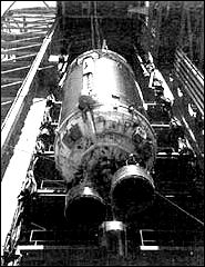
The Saturn program's association with the development of liquid hydrogen-oxygen engines officially commenced on 10 August 1960, when MSFC signed a contract with Pratt & Whitney for the development and production of at, engine, known as the LR-119, to be used in the S-IV and S-V stages of the C-1 vehicle envisioned in the Silverstein report. Designed to give 66 700 newtons (17 500 pounds) of thrust, the LR-119 was an uprated version of an early Centaur engine concept, the LR-115. Problems with the development of this new version led to the reconsideration of the original Centaur propulsion system, and in March 1961, the management of MSFC recommended the design of a liquid-hydrogen S-IV stage using the original LR-115 hardware. To compensate for the loss of thrust, MSFC decided to cluster six engines instead of four. On 29 March 1961, NASA Headquarters concurred, and the new six-engine cluster became the official configuration. In the course of development, Pratt & Whitney assigned various designations to the basic liquid hydrogen-oxygen engine. The final design, RL-10-A-1, replaced both the LR-115 and 119, and the RL-10 configuration became standard for both the Centaur and S-IV vehicles by 1961. An early version of the RL-10 design went through its first successful firing in August 1959, and by the winter of 1961, technicians finished the last of the RL-10-A-1 preflight rating tests. The engine's 66 700 newtons (15 000 pounds) of thrust performed 30 percent better than similar designs using hydrocarbon fuels. The A-1 designation identified a test article; on 9 June 1962, Pratt & Whitney finished the preliminary flight rating tests on the RL-10-A-3, intended for installation in operational flight versions of the second stage of the C-1 launch vehicle.16 The nation's first operational liquid hydrogen-oxygen engine was cleared for production.
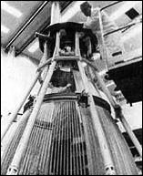
Pratt & Whitney engine design unquestionably benefited from the work at Lewis during 1953-1957, especially the virtues of regenerative cooling with liquid hydrogen.17 Pratt & Whitney added other innovative features. The Saturn program's RL-10 engines were mounted on the S-IV booster manufactured by Douglas as the second stage for the Saturn I. In physical terms, the RL-10 was about as tall as an average man. Its major components included the thrust chamber, fuel and oxidizer [138] turbopump assembly, liquid oxygen flow control valve, spark ignition subsystem, thrust control assembly, and miscellaneous control valves.
The contours of the nozzle configuration owed much to the influence of applied mathematics. Pratt & Whitney wanted a nozzle designed for optimum size and weight in relation to performance, but liquid hydrogen technology was so new that few ground rules were available. Applied math bypassed a lot of costly hardware experimentation, and Pratt & Whitney claimed that the procedures established during the effort became widely used within the rocket propulsion industry.18
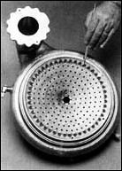
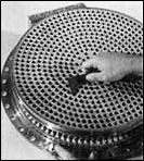
The injector, part of the thrust chamber assembly, featured a porous injector face, which was an important innovation. The RL-10 injector strongly resembled a large dish with a shallow, concave surface. Fabricated from material that looked like a heavy screen, the injector's propellant orifices poked through the mesh in concentric rings. The porous injector face did, in fact, consist of layers of stainless steel mesh, produced by a carefully controlled sintering procedure that caused the layers of mesh to become a coherent structure without melting. A controlled flow of gaseous hydrogen filtered through, cooling the injector face and reducing thermal stresses. The material, called Rigi-Mesh by its supplier (the Pall Corporation), apparently originated as a filter used in nuclear research. The product had been extensively used in hydraulic and pneumatic filters in aircraft and jet engines, where extreme vibration environments, high temperatures, and other operational requirements discouraged the use of nonmetallic filters. How Rigi-Mesh was first suggested for use in rocket thrust chambers is unclear. In any case, the Pratt & Whitney injector approach, using the porous mesh face, was a distinct improvement over conventional, flat-face injectors that Lewis Research Center had used.19
The fuel and oxidizer pumps were driven in a "boot strap" arrangement from a turbine assembly rated at 479 to 513 kilowatts. The propellant pumps consisted of a two-stage centrifugal fuel pump and a single-stage centrifugal oxidizer pump. General Dynamics/ Astronautics described the engine's turbopump as the key to operating the RL-10 production version, in which the "boot strap" sequence used gaseous hydrogen. At the start, liquid hydrogen trickled through the turbopump and down through the thrust chamber tubes of the regeneratively cooled engine. Even before the ignition sequence and main stage operation, the flowing liquid hydrogen became gaseous, and could be forced back through the turbopump with enough pressure to start it. This pressure set the hydrogen fuel pump in motion, and a gear train from the hydrogen turbine's main shaft began to drive the liquid oxygen pump-the "boot strap" sequence. After the start of combustion, the heat produced enough gas in the chamber walls to drive the high-speed turbine and also to maintain the combustion level.20
![the RL-10 statistics. [link to a larger picture]](p139as.jpg) |
.
|
 |
|
. |
|
|
![A schematic of RL-10 propellant flow. [link to a larger picture]](p139cs.jpg) |
|
|
|
. |
|
|
 |
|
 |
[140] This design offered two main advantages. First, the engine did not require a third propellant or a bipropellant to service a gas generator system (at a weight penalty) for the turbopump. Second, the designers obtained an efficient performance advantage because the hydrogen gases, after driving the turbine, were exhausted into the combustion chamber. All propellants, then, contributed directly to maximum thrust and highest specific impulse. The operation of the turbomachinery incorporated another interesting design feature. The RL-10 was the first production engine to use liquid hydrogen in place of conventional lubrication systems.21
During the test program, NASA and contractor personnel pushed the design to extremes to verify the engine's capability. Designed for a total firing time of 470 seconds, test engineers piled more than 3.5 times that duration onto one engine, running it for a total of 1680 seconds. Some of the test engines successfully operated through 5 to 70 separate firings with no maintenance or replacement of parts, equivalent in some instances to 10 round trips to the moon. "This philosophy of `limits' testing has proven successful in developing an engine with a high reliability and a high degree of confidence," explained key personnel in MSFC's engine program office. They characterized the pioneering RL-10 as a system of notable sophistication and versatility.22
Because of the known high-energy qualities of hydrogen as a fuel, modern rocket propulsion engineers manifested a continuing interest in liquid hydrogen as an attractive rocket propellant, able to lift payloads at a very favorable fuel-to-payload ratio. The potential of the liquid hydrogen RL-10 engine was encouraging; nevertheless, designers were thinking ahead of the RL-10's 67 000 newtons (15 000 pounds) of thrust to even heftier propulsion systems. In the fall of 1959, various NASA studies and contracts already included examination of 665 000-newton (150 000-pound) thrust engines, used singly or in clusters, which burned LOX and LH2. When very large space vehicles came into consideration, NASA began to revise its thinking toward even larger LH2-fueled engines for high-energy upper stages-engines rated at 890 000 newtons (200 000 pounds) of thrust. Such a remarkable goal achieved official sanction during the deliberations of the Saturn Vehicle Team, better known as the Silverstein committee, which finished its work and reported its recommendations to NASA on 15 December 1959.23
Following the Silverstein committee's recommendations, a source evaluation board was formed to nominate a contractor. The board included a pair of special teams-a technical evaluation team and a business evaluation team-to examine proposals on two separate levels. [141] Members, who met in Washington for six weeks, were chosen from Marshall, Lewis, and NASA Headquarters. The full board, chaired by MSFC's Hermann Weidner (a Peenemuende veteran and a senior MSFC propulsion engineer), submitted its final recommendation to NASA Administrator Glennan for approval. Glennan made the final announcement. In competition with four other companies, Rocketdyne Division of North American Aviation won NASA's approval on 1 June 1960 to develop a high-energy rocket engine, fueled by liquid oxygen and hydrogen, to be known as the J-2. Specifications for the liquid-hydrogen engine originated at MSFC, and the contractor then went to work on the initial design concepts and hardware. At every step of the way, the contractor and the customer (MSFC) exchanged information and ideas derived from earlier programs, modifying them for the requirements of the LH2 engine technology, and devising new techniques to implement the design goals of the new rocket powerplant.
The final contract, negotiated by Rocketdyne in September 1960, included an especially notable feature. For the first time, a high-energy, high-thrust rocket engine contract specified a design to "insure maximum safety for manned flight." Beginning with the first specifications through the subsequent stages of design, development, and final qualification, planning for manned missions became a mainline theme for Rocketdyne engineers. Other engines in NASA's space program stemmed from propulsion systems engineered for unmanned satellites or ballistic missiles such as the Vanguard, Redstone, Atlas, and Thor. From the start, exceedingly stiff reliability specifications for the J-2 reflected the engine's role in a manned mission. Reliability reviews began at the drawing board stage, and follow-up tests to verify the preceding test and design specifications continued in relentless succession. The technical management organization established to monitor the J-2 development consisted of three major groups. First, the design review board scrutinized each part of the J-2, analyzed it from a technical viewpoint, and investigated all of its design factors. Next, a reliability task force developed statistical methods tailored specifically to proposed test programs for the engine. Finally, all elements dovetailed in the Performance Evaluation and Review Technique (PERT), a reporting system used by the overall program management team.24
Rocketdyne launched the development of the J-2 with an analytical computer model that simulated engine operations and aided in establishing design configurations. One outgrowth of the model, a full-sized mockup with which to judge position of all components, remained an important tool throughout the J-2 program.25
[142] Rocketdyne's physical plant and long experience as a rocket engine manufacturer allowed the company to respond quickly. The main complex at Canoga Park, in the northwest sector of Los Angeles, combined engineering offices with elaborate laboratories for preliminary R&D. Development and production of the F-1 and the H-1 (and its immediate predecessor, the S-3D), coupled with extensive experimental work on advanced propulsion systems, equipped the company with excellent facilities and experienced R&D teams. Rocketdyne carried out J-2 firing tests and major-component tests at its Santa Susanna Field Laboratory, a rambling network of test stands and test cells set up in canyons and arroyos of the Santa Susanna Mountains, directly above the manufacturing area at Canoga Park. In days gone by, the canyon walls and gulches echoed with the drumbeat hooves of galloping horses and the sharp crackle of gunfire as Hollywood production crews cranked out yet another Western epic. Now the arroyo walls enveloped test beds for rocket engines, the steep slopes shielding the rest of the test areas and their crews in case something went wrong and an engine blew up. A visit to the surrealistic environs of Santa Susanna made a lasting impression. It was a tortured, sun-baked tumble of rocks and scraggly underbrush, with the separate test areas connected by long runs of piping for water and miscellaneous esoteric liquids required in rocket development. The pipes erratically twisted their way over the boulder-strewn landscape and up to the test fixtures-austere monoliths of concrete and stark steel girders jutting into the hot California sky. It seemed a fitting environment for the exotic world of rocket engine testing.26
Within two months of winning its contract, an R&D team put together the J-2's first experimental component, a full-scale injector. Using a temporary test facility at Santa Susanna, Rocketdyne technicians conducted the first hot-firing tests on 11 November 1960, to check out the workability of its design. In simultaneous programs, the company began developing means to test engines as well as engine components, modifying test stands as required. A large vacuum chamber to test engine subsystems under simulated space conditions was completed. By the end of 1960, the manufacturing planners, with an eye on problems encountered during the early design and phase, began to try to resolve some of the sticky manufacturing problems looming on the horizon. The schedule was obviously getting tighter as the research and development teams began the fabrication and assembly of the first experimental components and emplaced them in the test cells. Inaugurating Rocketdyne's first test facility built exclusively for the J-2 program, workers activated a component test cell in November 1961, and engineers began trial runs of the J-2 liquid hydrogen and liquid oxygen turbopumps. Early in 1962, only 18 [143] months after contract award, Rocketdyne conducted the first engine system test for ignition, lasting 2.57 seconds. The test unit used an uncooled thrust chamber with the turbopumps driven by externally supplied gaseous hydrogen, instead of using the engine's internal gas generator.
Drawing further on its considerable fund of experience in developing rocket engines for Army and Air Force programs, Rocketdyne personnel fabricated additional test components of the new J-2 in remarkably short order, and began to piece together the first experimental engine in the closing months of 1961. Technicians made final checks on the engine in the company's Canoga Park complex during January 1962 and stowed it on a truck, to be driven up the winding mountain to the Santa Susanna Field Laboratory. Short-run tests began the same month and continued through the summer. Technicians were achieving full-thrust testing of 50 to 94 seconds duration by early autumn, and on 4 October 1962, Rocketdyne successfully ran the engine through a long- duration test of 250 seconds.27
During the early developmental period in J-2 testing, the engine's place in Saturn rocket configurations also stabilized. In July 1962, NASA and Rocketdyne concluded contracts for continued development and formalized the production agreements for the J-2 through 1965. About the same time, NASA announced plans for a new two-stage vehicle, the Saturn C-1B (later the IB) for operations leading to Earth-orbital missions with a full-sized Apollo spacecraft.28 The J-2 engine was intended to power the S-IVB stage of two Saturn vehicles-the second stage of the Saturn IB and the third stage of the Saturn V. In addition, a cluster of five J-2 engines was also planned for the S-II second stage of the three-stage Saturn V vehicle, making the J-2 the most used cryogenic propulsion system in the Saturn program.
NASA and Rocketdyne signed a contract for 55 engines and development of appropriate support technology on 1 July 1962. Later in the month, Rocketdyne announced its plans for the construction of two new manufacturing buildings for the Saturn engines, including the J-2. The buildings were completed in record time; the company moved in just a year later. In November 1963, Rocketdyne began delivery of five engine simulators. Up to the point of actual firing, the simulators played an important role in the process of electrical and mechanical design of the ground support equipment furnished by Rocketdyne, and permitted technicians to work out the interfacing details involved in mounting the engine to the appropriate stage-the S-II stage manufactured by North American, or the S-IVB stage manufactured by Douglas. Ground support equipment, operating consoles, and special handling gear for the [144] engines and propellants were used in Rocketdyne's own manufacturing and test operations in California, at other test sites (Marshall and Mississippi Test Facility), and in launch operations at Cape Kennedy.29
Confident with the test results during 1962, Rocketdyne began to release the first production drawings to the manufacturing shops early in 1963. The J-2 engine emerged from the drafting boards as a self-contained propulsion system-a significant concept because the J-2 had to start in flight, shut itself down, then (in some versions) restart in orbit. Explaining the engine at a meeting of the American Institute of Aeronautics and Astronautics, Paul Fuller (Rocketdyne's project manager for the J-2 in 1965) stressed the effort given to the self-contained design philosophy. "The J-2 engine is not just a rocket engine supplying thrust for the vehicle, but is a fully integrated propulsion system" Fuller emphasized. "The engine provides all functions important to the vehicle's operation and mission capability." For this reason, engine and stage operation systems were closely integrated. To maintain tank pressure and still control the weight of the vehicles, the S-IV and S-IVB pressurized their fuel tanks by tapping hydrogen gas from the fuel manifold on the thrust chamber. To keep up pressure in the LOX tank, designers included a heat exchanger on the oxygen pump exhaust duct. In the S-II second stage, hot oxygen from the exchanger served as the pressurant, while in the S-IVB, stored helium ran through the exchanger and back into the LOX tank. These systems eliminated the need for other pressurants along with their extra weight and complexity.
The S-IVB, with a programmed restart in Earth orbit, included a "self-servicing" concept for the reignition sequence. The helium tanks included enough gas for the duration of the mission, but to get enough hydrogen gas to accelerate turbomachinery for the restart cycle, the engine system automatically diverted 1 kilogram of LH2 from the fuel system for storage in the depleted hydrogen start tank. To ensure proper functioning of the entire system during a mission, the engine's designers included integral instrumentation on the J-2 to monitor engine functIons on 72 different channels.30
For the integrated engine system philosophy, designers of the J-2 borrowed from many earlier liquid propellant engines, including the liquid hydrogen technology of the RL-10 program, and added a few innovations along the way. In the process, technicians and manufacturing engineers learned to cope with the problems generated by the J-2 as a newer and much larger generation of liquid-hydrogen engine systems.
Like the RL-10, the J-2 injector had to promote stable, controlled burning. But the 890 000-newton (200 000-pound) thrust J-2 burned [145] much greater quantities of cryogenic propellants than the 67 000-newton (15 000-pound) thrust RL-10. When Rocketdyne started work on the injector in 1960, the company tried a design familiar to its engineers, and built flat-faced copper injectors similar to LOX-RP-1 designs. The heat fluxes of LOX-LH2 designs turned out to be much different at the injector face, and the injectors started burning out. Bob Pease, an MSFC propulsion engineer who monitored some of the early tests, recalled that green flames shot out of one injector as the flame front started burning its way through the copper.
As one Marshall engineer observed, it was the general nature of a contractor to be reluctant to take on a competitor's innovation. Rocketdyne's injectors kept burning out, but the company seemed adamant against incorporating the porous injector face style of Pratt & Whitney's RL-10. Rocketdyne had been experimenting with this type of injector at NASA's insistence, and Marshall began to feel that their J-2 contractor needed a shove in this direction, instead of the persistent nudges delivered by MSFC up to this point. Lewis Research Center had all the information and hardware samples for the porous injector face. Jerry Thomson and other Marshall engineers dragooned Rocketdyne personnel into a special trip to Lewis in 1962 to look at the samples, and pressured Rocketdyne to use Rigi-Mesh in the injector face. With Rigi-Mesh adapted to the J-2, the problems of injector face burning disappeared.31
Still, Rocketdyne's larger engine and its operational characteristics presented difficulties in manufacturing. The successful design led to the next set of problems: how to "mass produce" a rocket engine injector with more than 600 uniform injection posts. After some trial and error, manufacturing engineers finally evolved a method of producing an injector with 614 uniform posts from a single piece of metal, using a special technique of electrical discharge machining. Fuel from the upper fuel manifold flowed into the combustion area through fuel orifices designed to be concentric with the oxidizer orifices. Design of the injector and angles of the orifices was calculated for highest combustion efficiency. As the hydrogen passed through the injector to the annular orifices, 5 percent of the flow seeped through the porous injector face, acting as a coolant to reduce thermal stresses created by the roaring combustion chamber.32
The J-2's thrust chamber consisted of several hundred steel tubes, designed and shaped according to data derived by computer. The computer helped solve the frustrating interplay of "the general energy equation, momentum equation, continuity equation, equation of state, and heat balance equation across tube walls." The readout of the computer proved to be very accurate, the final design of a tapered, formed tube bearing very close conformance with the original analytical model. Designers made optimum use of the marvelous facility of LH2 for heat transfer in designing the thrust chamber. [146] Fuel entered the chamber through a manifold at the chamber's midpoint, making a one-half pass down through 180 tubes on the outside, then up the inside of the chamber's throat in a complete pass through 360 tubes to the fuel injector. The liquid hydrogen entered the tubes at -253°C (-423°F) and warmed up in passage to "only" -162°C (-260°F), at which point it became gaseous. The design of the tubes permitted extremely wide variations in LH2 velocities, ranging from 18 meters per second at the bottom of the pass at the chamber's edge to 300 meters per second at the throat, and 240 meters per second at the injector entry ports. At different points within the tubes, cross sections varied correspondingly to accommodate changes in density and flow rates.33 With so many variables in the design, it is no wonder that the computer played such a pivotal role in engine development.
Turbopump design borrowed liberally from North American's experience in manufacturing jet aircraft engines and the early rocket engines for the Air Force. As in jet engines, the turbopump turbine blades featured a "fir tree" attachment technique. The bases of the blades were tapered and notched, giving them the silhouette of an inverted fir tree. Centrifugal forces in the turbopumps were terrifically high, and the notched blades kept them securely in place. From the Atlas program, Rocketdyne borrowed turbopump inducer designs and the inducer tunnel assembly, but many, many more components had to be conceived and fabricated to the characteristics of the new LOX-LH2 technology.
In designing the J-2 turbopumps to deliver propellants to the injector and the combustion chamber, the system was split into two different components, the LOX pump and LH2 pump mounted separately on either side of the combustion chamber. This approach avoided compromises in the efficiency of either pump and eliminated a complicated set of gears to run both pumps from a single shaft. On the LOX side, the J-2 used a radial pump, common to most rocket engines, which operated in the 6000 revolutions per minute range. The LH2 pump, by contrast, used a pump uncommon in large thrust engines, at the time-a seven-stage axial flow design with an operating capability of over 25 000 revolutions per minute. With proper calibration, the pumps delivered propellants to the thrust chamber at a rate of 2.3 kilograms of liquid oxygen to 0.4 kilogram of hydrogen.34
Power for the turbopumps came from a two-stage, velocity-compound turbine fired by a gas generator. The original design for the J-2 engine envisioned a "tank-head" start, in which pressure from the fuel tanks started the gas generator. Once in operation, the feed pressures and power increased as the turbopump attained its operational limits, drawing propellants from the tanks. The "tank-head" start was attractively simple but turned out to be too slow to be used in flight operations for the Saturn. So the turbine power system acquired augmentation for the spinup of the gas generator, using a spherical tank to store compressed [147] hydrogen gas with a storage capacity of 0.1 cubic meter. Gas from the hydrogen sphere started the gas generator and achieved rapid acceleration and operation from the start. This "gas-spin" start could be initiated at will during the flight, important for reignition of the S-IVB stage in Earth parking orbit. The only requirement involved a brief cycle during the engine run, in which hydrogen gas was tapped to recharge the hydrogen sphere.35 The design of the hydrogen storage tank constituted a unique feature of the J-2 engine: it incorporated a "tank within a tank," combining hydrogen storage with a helium storage tank. The helium, required for the pneumatic control system, tended to vent off unless kept under pressure at a low temperature. In a neat solution to the problem, Rocketdyne designed the helium storage tank as an integral unit inside the hydrogen start tank, and thereby saved space as well as weight. Both tanks were filled on the ground prior to launch-the outside tank with hydrogen, the inner tank with helium.36
The 1 1/2-pass fuel circuit permitted another design variation, in the disposal of the exhaust gas from the turbopumps. The gas delivered from the gas generator to the propellant turbopumps passed in sequence through the hydrogen axial flow turbines, then through a duct into the radial turbine of the LOX pump. The series arrangement yielded a very high efficiency and permitted easy control of the thrust and mixture ratios. Having already performed double duty in both the fuel and oxidizer turbopumps, the turbine gas exhausted into the thrust chamber to be used as fuel. In this way, the engine handled the turbine exhaust very conveniently and enhanced the engine's specific impulse at the same time.37
The high speeds at which the J-2's moving parts functioned required some special lubricants, which were acquired from the propellants themselves. Ball bearings in the turbopumps present special problems in lubrication- particularly the super-cold LH2 pumps. Normal lubricating oils proved troublesome because of the extremely low temperatures of cryogenic operation, so Rocketdyne built the LOX and LH2 turbopumps to have their ball bearings lubricated by the respective propellants. At Ohio State University, Herrick Johnston first demonstrated the potential of LH2 lubricants. The use of cryogenic lubricants in the RL-10 paved the way for this lubrication in the J-2.38
In May 1963, production lines for the operational model of the J-2 went into full swing, but concurrent testing programs at Rocketdyne and at MSFC were also maintained throughout the production run. Engineers from both the contractor and the customer were on hand when Douglas began firing up S-IVB stage hardware. The first production [148] engine, delivered in April 1964, went to Douglas for static tests on the S-IVB, battleship stage at the Douglas test facility near Sacramento, California.
The first full-duration static test of 410 seconds occurred on the battleship stand late in December. The mission requirements of the third stage for the Saturn V called for an application of 500 seconds, but each engine possessed a minimum usable life of 3750 seconds. Even so, the testing program often forced the engines beyond this. L. F. Belew, MSFC engine program manager, characterized the philosophy of "limit testing" as a combination of requirements for manned flight and cost control. "A major emphasis is placed on limits testing as a means of demonstrating reliability and confidence without a prohibitively large test sample," he explained.39
Intensive engine testing, including tests on MSFC's new S-IVB test stand in Huntsville, and flight rating tests of the 890 000-newton (200 000-pound) thrust engine for the Saturn IB and Saturn V at Santa Susanna Field Laboratory, continued throughout the summer of 1965. The last of the stringent qualification tests of the J-2 engine occurred from December 1965 into January 1966, conforming very closely to Belew's estimate. The J-2 proved its ability to perform well over its specified operational range. One engine ignited successfully in 30 successive firings, including five tests at full duration of 470 seconds each. The total firing time of 3774 seconds represented a level of accumulated operational time almost eight times greater than the flight requirements. As successful single engine tests moved toward their climax, integration tests of the propulsion system with the S-IVB accelerated with the availability of more production engines. Time schedules for testing the flight stages of the S-IVB became ever more pressing. The first operational flight, AS-201, was scheduled in early 1966 for the Saturn IB using the S-IB first stage and the S-IVB as the second stage.
At Sacramento, the first tests of S-IVB-201 in July 1966 were inconclusive when a component malfunction in one of the pneumatic consoles prematurely ended the test after a successful propellant loading and automatic countdown. Test conductors regained confidence on 8 August, when the S-IVB-201 performed beautifully on a full-duration firing of 452 seconds. The test commanded extra attention because of the first use of computers to control the entire operational sequence, including automatic checkout, propellant loading, and static firing.40 The successful test was no fluke. On 26 February 1966, AS-201 went through a flawless launch.
In July 1966, NASA confirmed J-2 production contracts through 1968, by which time Rocketdyne agreed to finish deliveries of 155 J-2 engines. The new contract included an uprated model of the J-2 engine with a thrust of 1 023 000 newtons (230 000 pounds). Rocketdyne began work on the uprated version in 1965 and delivered the first engine to [149] MSFC for testing during the spring of 1966. Mission planners intended to use the new engine in the second stage of the Saturn IB beginning with AS-208, as well as the second and third stages of the Saturn V beginning with AS-504. Meanwhile, an intensive test program continued. Following a preliminary series of simulated altitude tests using Rocketdyne facilities, a more stringent series of tests was conducted using the advanced equipment of the Arnold Engineering Development Center. The center was run by the Air Force at Tullahoma, Tennessee, not far from MSFC. Specialists at Arnold ran a series of altitude tests on J-2 engines for the S-IVB/IB stage and followed up with an equally successful test series on engines for the S-IVB/V in March 1967. Using facilities that duplicated temperatures and environmental conditions at 305 000 meters, Arnold cooperated with NASA on a string of initial start, stop, and the crucial reignition sequences. Throughout the year, Rocketdyne continued to test and verify the J-2 reliability at Santa Susanna. The company's research and development program included 203 separate tests on the J-2, accumulating a total of 33 579 seconds of firing time. In a concurrent program, production engines from the assembly lines in the valley kept rolling up the mountainside in trucks for their production qualification tests.41
Development of the J-2 engine turned up the inevitable gaggle of problems to perplex project designers, engineers, and workers. In using cryogenic propellants, it was obvious that great care was needed to ensure installation of very efficient insulation at critical points to control thermal losses. In the case of most early rocket technology using LOX as the oxidizer, the problem was not immediate. Designers simply took advantage of the fact that LOX components had a tendency to frost over. The frosty coating worked surprisingly well as natural insulation-so well that many components were designed without insulation from the start. The super-cold liquid hydrogen permitted no such easy design shortcuts. When air touched the extremely cold LH2 surfaces, it did not frost, but actually liquified. As a result, streaming liquid air not only became an annoyance, but also created a serious heat leak. For J-2 parts operating with LH2, it became imperative to provide adequate insulation. Vacuum jackets sufficed for most of the liquid hydrogen hardware, and similar treatment, or moisture-sealed insulation, worked for pump fittings and ducts. The main LH2 inlet duct, however, presented a more intricate challenge. The duct had to move with the gimbal action of the engine through 10.5 degrees, maintaining a full flow of fuel all the while. With a diameter of 20 centimeters, and a length of 53 centimeters, the duct also experienced extension and compression of -11.4 centimeters, with a [150] twisting, angular movement. The final design featured a vacuum jacket built like a double bellows, stabilized with externally mounted scissorlike supports. Top engine program managers from NASA agreed that the vacuum-jacketed flex inlet lines marked a significant design achievement in the J-2.42
The prickly, minute, intricate problems of liquid hydrogen technology followed the design engineers down to the last details of the J-2, including the myriad of joints where different ducts, tubes, and lines met each other or fastened to specified engine parts. At each juncture there existed the danger of an LH2 leak and a devastating explosion. Rather laconically, W. R. Studhalter, one of Rocketdyne's engineers in the J-2 program, summed up a tedious, frustrating job. "The static seals for hydrogen had particular design attention," he said, "not only to prevent loss under vacuum operation, but to prevent hazardous mixing of hydrogen with air during sea-level testing and handling." To alleviate sealing complications, he continued, "the engine design has concentrated on the elimination of joints requiring sealing by a uniquely complete utilization of welded connections." Some seal points were not suitable for welding, and with specifications for zero-measurable leakage, the J-2 team met the problem with a device known as a "pressure-actuated combination seal." "This seal has such excellent demonstrated performance that it is used throughout the J-2 engine," said Studhalter, "not only for liquid hydrogen but for liquid oxygen, helium, and generator gas." The J-2 had 112 various seals, mostly for instrument connections. Most were small, although the biggest installation required a comparatively large unit for the thrust chamber-injector seal point.43
Modifications never seemed to end. Marshall engineers noted that they could test components to exhaustion, but "you would never know for sure they would work until you put them together in the engine." Even if two engines tested successfully, a new problem might show up on the third. There was a lot of "cut-and-try" work to solve these complications, and the engine men admitted that they were not always sure which "fix" corrected a problem-or created a new one. The engineers were reconciled to a process of changes, of trying to find out what went wrong (or what could go wrong), and trying to correct the difficulty. "Happiness should be finding a failure, rather than not finding a [potential] failure," said MSFC's Bob Pease. It was accepted that many problems would be caught after the engines were already in production. The Saturn program always needed production hardware to meet schedules, and the stage contractors needed engines as early as possible to verify the fuel system, electronic compatibility, and so on. For these reasons, drawings for production engines were released, even though test engines were still exhibiting failures. Engineers expected to find solutions and crank necessary changes into the production line. Occasionally, modification kits were dispatched to engines in the field.44
![The J-2 liquid-hydrogen-fueled engine statistics [link to a larger picture]](p151as.jpg) |
.
|
 |
|
. |
|
|
![A schematic of the J-2 engine systems [link to a larger picture]](p151cs.jpg) |
|
 |
|
. |
|
|
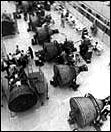 |
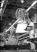
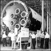
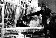
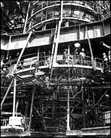
The J-2 liquid-hydrogen-fueled engine: statistics are presented at top left; at top right, the J-2's injector; above, left, a schematic of the J-2 engine systems; above, Rocketdyne workmen in a "clean room" in the Canoga Park plant are stacking the coolant tubes that will form the wall of a J-2 engine thrust chamber; at left, final assembly of J-2 engines at Canoga Park- J-2s for both the Saturn IB and the Saturn V; below, left, engineers study a J-2 engine that has simulated frigid space conditions; below, right, a cluster of five J-2 engines are readied for firing at Santa Susanna. | |
|
. |
|
|
 |
. |
 |
[152] Various areas of concern in the production of the engine, such as reorganizing the gas generator system sequence to refine the LOX flow and halt burned-out gas generator walls, cropped up along the way. A more serious problem concerned the tendency of the fuel pump to stall. After considerable investigation, researchers isolated the problem as one of excessive gas buildup in the thrust chamber. With the J-2's regenerative full flow mode, a substantial volume of hydrogen gas was created when the first fuel passed through the comparatively warm chamber. The amount of this gas exceeded the rate of flow designed into the injector, and this impeded the rate of flow of fuel downstream in the system while the engine was starting. To solve the problem, the designers developed the prechill sequence for the chamber and pumps alike and established temperature condition limits for the engine before attempting a start. In these and other engine difficulties, Marshall and Rocketdyne applied all the latest analytical methods and computer programs. It still came down to the issue of making an adjustment, however, and then trying it out to see what happened.45
Rocketdyne officials hoped to utilize existing engine facilities to test the J-2 engines and components. The unusual characteristics of liquid hydrogen engines generated an excess of problems in the test equipment- valves, transfer lines, and tanks designed for the earlier liquid oxygen technology. To use LH2 at -253űC, the available equipment had to have its materials rechecked for insulation, sealing, and embrittlement with the new fuel. In 1961, Rocketdyne established a special cryogenic laboratory to devote its attention exclusively to LH2 paraphernalia. The difficulties extended to numerous items of equipment such as the piping for the LH2 test-run tanks. A typical test installation included three cryogenic tanks, one with a capacity of 307 000 liters (90 000 gallons) of LH2 and two smaller tanks each holding 73 000 liters (20 000 gallons) of LOX. The LH2 tank was a conventional pressure-vessel type, with the addition of a complete vacuum jacket of unusually large design. The liquid hydrogen transfer pipes at the test installation likewise required the vacuum jacket treatment. For years, engineers relied on a double-wall design in transfer pipes that used a bellows in the inside pipe to absorb expansion and contraction. The interior bellows segment presented difficult maintenance problems under normal cryogenic conditions-problems that became pernicious with the introduction of liquid hydrogen. Rocketdyne sought a new approach, and after rejecting a number of candidates, adopted a piping design based on the use of Invar, an alloy pipe with very low expansion characteristics. At the time, the use of Invar piping for such extensive cryogenic operations was the exception to the rule, and the company perforce had to engage in extensive evaluation programs. In its application by Rocketdyne, the use of Invar was "reduced to practice." Invar's virtually negligible thermal contraction permitted long inner pipe runs with no expansion mechanism at all [153] (although the stainless steel outer jacket retained a bellows section for thermal movement). Rocketdyne installed 8- centimeter and 9-centimeter pipe sizes in runs of up to 370 meters and used some welded pipe of up to 25 centimeters in diameter. Technicians also perfected methods for reliable ship welding and field welds of Invar at the test sites.46
The differences in thrust and mission requirements gave the RL-10 and J-2 distinctive variations in operating methods and specific details of design. In other ways, there were interesting similarities. In retrospect, the development of the RL-10 and J-2 engines progressed with remarkably few serious hassles. The liquid-hydrogen-fueled engines, just like RP-1-fueled engines, experienced a normal rash of complications and problem phases. It is worth noting that despite the F-1's size and attendant vicissitudes, Rocketdyne was fortunate in having the experience of its H-1 engine development as a base. Although the liquid hydrogen engines were developed and built by two different contractors, the government managed both programs so that information from one program was available to subsequent programs. Lewis Research Center, NASA's facility in Cleveland, represented an interesting intermediary influence, providing a pool of knowledge about liquid hydrogen technology used by Pratt & Whitney and Rocketdyne alike. Just as early work at Lewis was a benefit to Pratt & Whitney's RL-10, Rocketdyne's later J-2 benefited from both Pratt & Whitney and Lewis.
It has been noted that engine development normally preceded development of the stages, and that the engine program often became the pacing item. The Saturn program generally reflected this trend, although at one point it was a stage, not an engine, that threatened to disrupt the tight schedule of Apollo-Saturn.