SP-4206 Stages to Saturn
[87] The H-1 engine traced its ancestry to postwar American development of rocket propulsion systems, and the opening section of chapter 4 includes an assessment of this engine's technological heritage. While the development of other engines discussed in Part Three differed in specifics, the overall trends in their design, test, and achievement of operational status paralleled that of the H-1 and sprang from the same evolving technology. Introduced on the Saturn V, the giant F-1 engine, while more akin to the conventional cryogenics of the H-1, experienced many development problems. The problem of scale affected many aspects of Saturn hardware development, as the F-1 story attests.
Application of liquid hydrogen (LH2) technology constituted one of the key aspects of Apollo-Saturn's success. The upper stages of the Saturn I and Saturn IB introduced LH2-fueled RL-10 and J-2 engines, respectively, as discussed in chapter 5.
[89] Development of rocket engines was usually conducted several steps ahead of the stage's tankage and the stage itself. This was done because of the inherent complexities of propulsion systems and inherent difficulties in engine research and development. Moreover, the choice of engine propellants influenced many elements of stage design, including the location of fuel and oxidizer tanks, propellant lines, and the various subsystems involved in the interface between the engine and stage.
Much of the ultimate success of the Saturn launch vehicles depended on the application of cryogenic technology-the use of liquefied gases in propellant combinations. The first-stage engines of the Saturn I, Saturn IB, and Saturn V (respectively, the S-I, S-IB, and S-IC stages) used a noncryogenic fuel called RP-1, derived from kerosene. All Saturn's engines used liquid oxygen as the oxidizer, and the engines of the S-IV, S-IVB, and S-II stages relied on liquid hydrogen as fuel. Put simply, the ability to carry large amounts of cryogenic propellants meant much more efficient launch vehicles. If designers had tried to build a rocket large enough to carry gaseous propellants, the size and weight of the tanks would have made it impossible to construct and launch such a vehicle. With the gaseous propellants converted to a liquid state, requiring less volume, designers had the opportunity to come up with a design capable of getting off the ground. In the 1960s, cryogenic technology experienced a phenomenal rate of growth and state of development. In support of the space effort, scientists and engineers accomplished a number of major breakthroughs, not only in the field of cryogenics itself, but also in the design and production of cryogenic rocket engines.
[90]
![SATURN ENGINE APPLICATIONS.[link to a larger picture]](p90s.jpg)
The scope of cryogenics was neatly summarized in a NASA report on cryogenics and space flight:
Cryogenics is the discipline, that involves the properties and use of materials at extremely low temperatures; it included the production, storage, and, use of cryogenic fluids. A gas is considered to be cryogen if it can be changed to a liquid by the removal of heat and by subsequent temperature reduction to a very low value. The temperature range that is of interest in cryogenics is not defined precisely; however, most researcher consider a gas to be cryogenic if it can be liquefied at or below -240°F. The most common cryogenic fluids are air, argon, helium, hydrogen, methane, neon, nitrogen, and oxygen.1
In the early post-World War-II era, as the United States' military services struggled to develop their own stable of launch vehicles, they leaned very heavily on the German wartime experience in technical areas [91] beyond the basic design of vehicles and rocket engines. Although a reasonable amount of cryogenic technology was available in the United States by World War II, there was little experience in applying it to rocketry. Goddard's work in cryogenics was apparently overlooked or inappropriate to the scale demanded by the ICBM program.
The development of the intercontinental ballistic missile (ICBM) required a host of subsidiary technological advances, in such areas as cryogenic fluid systems, insulation, handling and loading propellants, and large storage dewars. As some American experts admitted later, "Initially, the basic V-2 cryogenics data were used because the data constituted the sole candidate for consideration at the time." Eventually, the United States built up its own storehouse of cryogenic technology for rocket development. The ICBM program and other research by civilian agencies prompted greater interest for governmentally supported research, and the Cryogenic Laboratory of the National Bureau of Standards in Boulder, Colorado, opened in 1952. By that date, cryogenics was firmly established as an industrial and research discipline, ready to support military requirements and the American space programs, particularly in the 1960s.2
The role of cryogenics in American launch vehicles increased steadily, starting with the liquid-oxygen oxidizer of the Vanguard first stage. Other rockets like the Redstone (and its derivatives), Thor, Atlas, Titan I, and finally the Apollo-Saturn series of launch vehicles-the Saturn I, Saturn IB, and Saturn V-used cryogenic oxidizers, fuels, or both.3 As in so many engineering achievements, engine development for the Saturn program represented the culmination of earlier R&D efforts, as well as the improvement of earlier production items. The large vehicle boosters of the Saturn program borrowed liberally from the accumulated engine technology of the ICBMs and the intermediate range ballistic missiles (IRBMs) developed for the military, particularly the Thor and Jupiter IRBM programs as well as the Atlas ICBM.4 The H-1 traced its general lineage to no less than five prior designs: the control valves, gas generator system, turbopump assembly, and thrust chamber derived specifically from hardware applied in the Thor, Jupiter, and Atlas engine.5
Thrust increased dramatically, from the 120 000 newtons (27 000 pounds) of Vanguard's first stage in 1959 to the 33 000 000-newton (7 500 000-pound) first-stage booster of the Saturn V in 1967. The fantastic jump in thrust levels was accompanied by gains in the specific impulse (a measure of efficiency of a rocket propellant, equal to the amount of thrust obtained per pound of propellant burned per second), [92] especially with the introduction of liquid-hydrogen engines on the upper stages of the Centaur and Saturn launch vehicles, a major achievement of the American space program. Concurrently, advances were essential in a number of supporting technologies-lightweight components, compact packaging, materials application, and fabrication procedures. Propulsion system designers and engineers accumulated considerable experience along the way and refined various elements of the engine for better operation and introduced more sophisticated components and better control systems. Taken together, a myriad of improvements through research and development after the end of World War II contributed to higher levels of good engine design, with higher specific impulses, thrust stability, and flexibility in operational status.6
A review of engine advances achieved by the mid-1960s can effectively characterize the accomplishments leading up to the Saturn and highlight the innovations that were actually incorporated into the Saturn propulsion systems. Problem areas, which limited the desired performance of these engines, received special attention from a wide variety of research programs. Many improvements stemmed from the research programs carried out by industry. Many more evolved from the cooperative efforts generated by NASA and the various military services. The primary technological advances can be summarized under the following categories: thrust chambers, turbopumps, and system design and packaging.
Many early liquid-propellant engines featured a conical nozzle. Engineering improvements in thrust chambers were aimed at more efficient shapes for increased performance and decrease in weight. Designers sought higher performance through higher area-ratio shapes with higher chamber pressures to minimize the size and weight of the thrust chamber. In the drive to produce large, high-pressure engines, a major hurdle was a satisfactory means to cool the thrust chamber. An early solution used double-wall construction; cold fuel passed through this space en route to the combustion chamber, thereby reducing the temperature of the inner chamber wall. But design limitations restricted coolant velocity in the critically hot throat area of the engine. Thin-walled tubes promised an ideal solution for the problem of the thrust chamber walls. Tubes reduced wall thickness and thermal resistance and, more importantly, increased the coolant velocity in the throat section to carry off the increased heat flux there. As chamber pressures continued to go up along with higher temperatures, designers introduced a variable cross section within the tube. This configuration allowed the tube bundle to be fabricated to the desired thrust chamber contour, but variations in the tube's cross section (and coolant velocity) matched the heat transfer at various points along the tube. The bell-shaped nozzle permitted additional [93] advantages in reducing size and weight when compared with what engineers called the "standard 15-degree half-angle conical nozzle." Without any reduction in performance, the bell shape also permitted a 20 percent reduction in length.
Advances in one area of the propulsion system created demands on other parts of the system. As thrust levels and pressures increased, so did demands on the turbomachinery to supply propellants at greater flow rates and higher pressures. Problems concerned the development of higher powered turbomachinery without increases in size or weight. Advances in turbomachinery design centered on higher speeds, and the goal of higher speeds encouraged the introduction of rotating components with smaller diameters. Essential subsidiary improvements dealt with high-speed bearings, the performance of high-speed inducers, and higher speeds for the impeller tips. Engineers succeeded in increasing the operating speed of bearings through minute attention to details of the operating environment and the fabrication of bearing parts. Designers reconsidered and redesigned bearings for their optimum size, the contact angle of surfaces touching the bearing, and the curvature of the race structure. Better performance was gained by engineering the newly designed bearings for combating contact fatigue and wear from overheating. Further refinements included the introduction of new, high-strength materials and improved surface finishes in the fabrication of precision parts. The innovative use of the engine's own propellants as "lubricants" was another advance. Although the propellants were not lubricants in the usual sense, they served the same purpose. The properties of the propellant-lubricants were more important in carrying off frictional heat to keep pump bearings cool and operable. This application simplified turbopump operation and eliminated the need for externally supplied lubrication.
Engine designers also attacked propellant cavitation, a condition in which the formation and collapse of bubbles or vapor pockets while pumping the propellant caused vibrations and damage to rocket machinery. Study programs found how the cavitation characteristics were related to the inducer through such minute factors as the angle of blades, taper, blade sweep, and the profile of the leading edge. More accurate theories on the phenomenon of cavitation enabled a redesign of the inducers that doubled their suction. The overall increase in suction efficiency of the turbopump permitted the pump to operate at higher speeds. This contributed to weight savings in the vehicle because tank pressures-and tank weight-could be lowered. The higher operating speeds and pressures triggered development of pump impellers to [94] operate with higher tip speeds. The infusion of high-strength materials, plus design improvements and fabrication techniques paid off in reliability and greater speed. In total, all of these developments enhanced the incremental gains in power-to-weight ratios.
Over a brief span of time, the packaging and design of cryogenic rocket engines made dramatic progress. The size of the thrust chamber increased, while the "packaging" (pumps, turbomachinery, and related systems) remained relatively constant or actually decreased in physical size. At the same time, efficiency and design advantages accrued. In the early Redstone days, builders situated the turbopump, propellant lines, and controls above the thrust chamber and achieved directional control by the use of jet vanes. When gimbaled (movable) thrust chambers appeared on the scene, the design limitations of pumps, lines, and other paraphernalia dictated their attachment to the more solid footing of the vehicle's thrust structure. With the thrust chamber as the only movable part of the engine, engineers had to develop a new high-pressure feed line, with great flexibility, to link the propellant pumps to the thrust chamber. As the rise in chamber pressures and thrust levels put increased strains on the high-pressure lines, designers began studies of systems design and packaging to permit mounting the turbopomp and associated gear onto the thrust chamber itself. In this configuration, the pump and chamber could be gimbaled as a single unit, permitting the installation of [95] low-pressure "flex lines" between the pump inlets and the vehicle tanks. As it so happened, improvements in the design and efficiency of turbomachinery already made it compact and reliable enough to justify relocation on the thrust chamber.7
In many ways, the H-1 was a composite example of rocket engine development in the 1950s, modified and improved for its role in manned launches of the Saturn I and Saturn Ib. Even though the H-1 was derived from a propulsion system already in production (the S-3D engine for the Thor and Jupiter), requirements for increased thrust and generally improved performance led designers and engineers into new and frustrating problems. The evolution of both the H-1 and the F-1 engines fell into the pattern of many launch vehicle development programs, in which the engines constituted the pacing item.8 Furthermore, the difficulties in engine design were usually predictable, as Leonard C. Bostwick, a veteran MSFC engine manager, knew all too well. "The development of liquid rocket engines followed similar patterns regardless of engine size," he asserted. Despite this ability of the engine managers to look with a crystal ball into the future, ability to avoid all expected pitfalls did not follow. "In the development of liquid rocket engines, problems occur at several distinct intervals," Bostwick continued. "The type of problem and the time phase can be predicted, but since the exact nature of the problem cannot be so readily defined, a five to seven year development program becomes a necessity."9 In general, an engine development program progressed through four distinct problem phases" over the five- to seven-year period.
The designers of each successive generation of rocket engines commenced their work with facts and figures accumulated-often painfully-from earlier designs and experience. If, however, the new engine was expected to perform better than the old ones, the designers very quickly found themselves in uncharted territory. They proceeded to push ahead of the state of the art, seeking more flexibility in operations, greater simplicity, increased thrust, and improved overall performance. At this point, Bostwick pointed out, "The first problem phase occurs because of the inability to totally extrapolate and build on existing knowledge." Just as problems were predictable, so were the problem areas. Bostwick was specific: "The problems will occur in the combustion mechanics, propellant movement, or in the propellant control system." The hardware evolved for this early development period often proved to be less than adequate, and faults would sometimes not show up until the engines moved past the initial firing sequence tests, perhaps in the late tests to maximum projected duration and thrust levels. When the [96] problems then showed up, they were "often catastrophic," Bostwick wryly observed. For this reason, the engines were subject to extensive test programs to expose their inherent frailties.
Some time after the engine had successfully passed qualification tests of the basic engine design, or even the preflight rating trials, the second cycle of problems appeared. The difficulties involved the mating of the propulsion systems to the vehicle or stage. Because the development of the engines usually preceded the development of the stage by two or three years, the engines would not fit the mounting hardware and multitudinous connections with the stage. In addition, there were the peculiarities of late changes in the stage-engine interface requirements or possibly in the operational environment introduced by new variations in the flight plans. The stage contractors received prototypes or preflight-rated engines and cooperated with the engine interface. Inevitably, new sets of variables, which could not be anticipated from mating with a nonexistent stage or for changes in mission requirements, created problems.
As the engines phased out of the developmental stage and into full production, MSFC personnel and the manufacturer turned their attention to the third round of problems. They watched the elements of quality control, tolerances in the manufacturing of components, vendor selection, choice of manufacturing materials, and definition of the integral manufacturing process. "A continuing development program is planned during the period," Bostwick explained, "to provide the trained personnel, facilities and hardware capabilities to investigate these problems and to prove out the required corrective effort.
Defying all these attempts to identify potential failures, to uncover and correct weaknesses before a multimillion-dollar vehicle left the launch pad, actual missions inevitably uncovered a fourth set of problems, because there was no way to duplicate the actual environment in which the vehicle had to perform. With launch dates carefully scheduled ahead of time to coincide with the launch "windows" and carefully paced to the requirements of the Apollo-Saturn program, the problems uncovered by one mission demanded a very fast response to keep the next phase of the program on schedule. For this reason, NASA and the contractors maintained a well-staffed cadre of specialists at the contractors' engineering and test facilities, backed up by the facilities available at MSFC.
With the four major problem phases successfully handled, the need for ongoing development and engineering monitoring continued. "When engine systems are tested to longer durations and more extreme limits," warned Bostwick, "problems are uncovered that may have existed for a long time but were not evident until the more severe testing on a larger engine sample produced the failure mode." Other factors entered the picture too, such as changes in process, improvements in manufacture, or [97] changes in vendors, any or all of which could create a problem in quality of the hardware or introduce a different and incompatible material."10
Despite the best intentions of all concerned, engine development and production encountered predicaments throughout the duration of the Saturn program.
With requirements for the first generation of Saturn launch vehicles established in general terms, planners began to consider the development of propulsion systems. To save time and money. NASA opted for an effort firmly rooted in existing engine technology. The result was a decision to modify the Thor-Jupiter engine, the 667 000-newton (150 000-pound) thrust S-3D and uprate the engine to a thrust of 836 000 newtons (188 000 pounds). On 11 September 1958, NASA awarded the contract for the uprated engine to Rocketdyne, the original supplier of the S-3D engines for Thor and Jupiter. In the beginning, engineers designed the H-1 for a clustered configuration to gain higher thrust than could be obtained from any existing single engine. The basic concept featured four fixed inboard engines and four outboard engines with gimbal mounts to provide attitude control for the vehicle.11
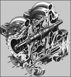
Although the original specifications called for 836 000 newtons (188 000 pounds) of thrust, the first models were delivered at 734 000 newtons (165 000 pounds) of thrust-down rated for greater reliability. Eventually, the H-1 engine served the first Saturn vehicles in four separate versions: 734 (165)-, 836 (188)-, 890 (200)-. and 912 000 newtons (205 000 pounds) of thrust. Saturn I used the 734 (165) and 836 (188) engines in clusters of eight; Saturn IB mounted eight units of the 890 (200) model in vehicles SA-201 through SA-205, with the 912 (205) model earmarked for SA-206 and subsequent vehicles. The engines all had the same approximate dimensions, standing 218 centimeters high, with a radius of 168 centimeters at the throat. The H-1 engines incorporated a tubular-walled, regeneratively cooled thrust chamber. The propellant was supplied by twin pumps, driven through a gearbox by a single turbine, which was powered in turn by a gas generator burning a mixture of the vehicle's main propellants.12
Because the engine's basic design was kept to existing components and propulsion systems, Rocketdyne got off to a running start; the first 734 000-newton (165 000-pound) thrust prototype came off the drawing boards, was put together in the contractor's shops, and static-tested by 31 December 1958, less than four months after the contract was signed. Development proceeded rapidly; by the spring of 1960, NASA had performed the initial test of the eight-engine cluster, and the H-1 passed the Preliminary Flight Rating Tests by the fall of the same year. These [98] milestones demonstrated the basic ability of this version of the H-1 to meet the flight requirements, and on 27 October 1961, vehicle SA-1 was launched successfully. Close on the heels of the 734 000-newton (165 000-pound) thrust engine, NASA and Rocketdyne initiated work on more powerful models; intended for later Saturn I missions, the 836 000-newton (188 000-pound) version of the H-1 went through its preliminary flight-rating test on 28 September 1962.13
For the S-IB first stage of the Saturn IB launch vehicle, MSFC began studies for uprated engines with Chrysler, the first-stage contractor. In November 1963, Chrysler returned its analysis of engine load criteria and suggestions to mesh the schedules for engines and stages. On this basis, MSFC directed Rocketdyne to go ahead from the more powerful 890 000-newton (200 000-pound) thrust engine to a 912 000-newton (205 000-pound) thrust system for the most advanced missions contemplated for the Saturn IB. The schedule for engine deliveries stretched out through 1968, when, on 30 June 1967, Rocketdyne signed a contract calling for a final production batch of 60 H-1 engines, bringing the total number purchased to 322.14
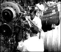
Testing for the H-1 engine occurred in several widely separated areas. Initial development took place in the engineering facilities at Rocketdyne's main plant in Canoga Park, California. In the nearby Santa Susana Mountains, the company used one engine test stand, known as Canyon 3b, for early development testing. For component testing, single-engine tests, and clustered-engine tests, the H-1 program depended on facilities located at Marshall Space Flight Center in Huntsville. Installations at MSFC for H-1 development included a component testing laboratory, a gas generator test stand, a single-engine test stand, and a full-sized booster test stand for engine cluster tests. At Rocketdyne's primary manufacturing complex for the H-1, located in Neosho, Missouri, the company relied on existing installations for manufacture and acceptance testing. Two dual-position test stands were available, built for the original purpose of checking out engines manufactured for Air Force missiles. A rental agreement, negotiated by NASA and the Air Force, permitted Rocketdyne to use one position on each of the dual stands.15
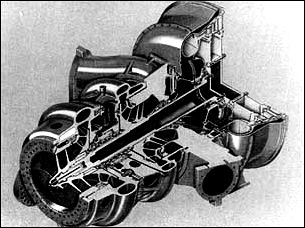
The models of the H-1 used in the Saturn I and Saturn IB shared the same seven major systems: thrust chamber and gimbal assembly, exhaust system, gas generator and control system, propellant feed system, turbopump, fuel additive blender unit, and electrical system. Production of the H-1 propulsion system involved several design aspects unique to the Saturn program. For example, the Saturn H-1 engine came out of Rocketdyne's shops in two slightly different models. Each unit had a gimbal assembly for attachment to the vehicle, but the inboard engines, [99] not required for thrust vector control, were immobilized by struts which held them rigidly in place. The outboard engines were equipped with gimbal actuators, attached to outriggers on the thrust chamber, that produced the gimbaling action for directional control for the vehicle. Basically identical, the inboard and outboard engines possessed an additional physical difference that necessitated a different label for each. The exhaust system varied for the outboard and inboard engines, although both types mounted a turbine exhaust hood, a turbine exhaust duct, and a heat exchanger (with a coil system to convert liquid oxygen to the gaseous oxygen required to pressure the oxygen tanks). The H-1C engine, the fixed inboard unit, had a curved exhaust duct to carry the turbine exhaust gases, and the H-1D engine, the gimbaled outboard unit, mounted a unit known as an aspirator. The inboard engines simply ducted the turbine exhaust overboard. The outboard engine exhaust was ducted into collectors, or aspirators, located at the exit plane of the nozzle. For the H-1D aspirator, designers chose a welded Hastelloy C shell assembly, mounted on the outside of the thrust chamber and extending beyond the thrust chamber exit plane. The aspirator prevented the fuel-rich exhaust gases of the gas generator from recirculating into the missile boat tail during flight. Instead, the gases merged into the engine exhaust plume.
As developed for the Saturn program, the H-1 also shed a number of accessories carried over from the Jupiter engine system. Early versions of the H-1 relied on the Jupiter's lubrication system, which featured a 73-liter (20-gallon) oil tank. The H-1 designers arranged for the vehicle's own fuel, RP-1 (along with some additives), to do the same job. This arrangement eliminated not only the oil tankage, but also a potential source of contamination. The new approach required a fuel additive blender unit as part of the engine system, tapping RP-1 fuel from the fuel turbopump discharge system. During development, the H-1 shed other remnants of its heritage from the Jupiter. A single-engine ballistic missile needed complex thrust controls to ensure its accurate impact on target. The Jupiter, perforce, carried considerable ancillary baggage to accomplish its mission-pressure transducers, magnetic amplifiers, hydraulic servo valves, and a throttling valve for the gas generator and liquid oxygen. The H-1 engine, by contrast, relied on simple, calibrated orifices within the engine, because thrust control requirements were much less severe when individual engines were clustered. In the Saturn, this permitted a marked simplification of the H-1, accompanied by an attendant gain in reliability.16
Lee Belew, manager of the Engine Program Office at MSFC, noted four major development problems during the H-1 era. These included.....
[100]
![The H-1 engine statistics are shown. [link to a larger picture]](p100as.jpg) | ||
|
. |
|
|
![the sketch shows the drive for simplification of the H-1 engine from its parent S-3D.[link to a larger picture]](p100bs.jpg) | ||
|
. |
|
|
|
| ||
|
. |
|
|
 |
. |
 |
[101] ....combustion instability (or combustion oscillation, at he called it), cracks in the liquid oxygen dome, thrust chamber tube splitting, and problems with the pump gears and bearings. Other difficulties made their appearance, and each required a different kind of troubleshooting to solve the case.
The term "combustion instability" described an unsteady or abnormal combustion of fuel, a condition that not only reduced engine performance, but could destroy the engine-and the rocket as well. Within NASA and contractor circles, there was early concern about the potential problem of combustion instability, particularly in the uprated engines for Saturn I and the even larger engines planned for the Saturn V. Investigators deliberately set out to introduce combustion instability in the H-1 to see if the engine could recover, and if not, redesign the engine to overcome this potential danger. Late in 1963, a research group evolved a technique to induce combustion instability. Workers fixed a special boss to the face of the injector, and attached a small, 50-grain bomb to it. Enclosed in a cylindrical nylon case designed for initial cooling by engine fuel, the bomb was protected during engine start and run up but soon heated up, and after a time, it ignited. The explosion disturbed the combustion flame front sufficiently to create an unstable operating condition. It was hoped that the injector could recover from the instability in less than 0.1 second, but the Thor-Atlas injectors, uprated to 836 000 newtons (188 000 pounds) of thrust, failed to effect recovery in 8 of 16 bomb tests. After some research and development work, designers rearranged the injector orifices and added some baffles to the face of the injector. The new design worked beautifully, giving satisfactory recovery at various thrust levels and an unexpected bonus-an actual increase in engine performance.17
Another problem required changes in several flight vehicles. While vehicle SA-7 was undergoing a series of leak checks at Cape Kennedy in the fall of 1964, technicians came across a crack in the LOX dome of an H-1 engine mounted on the first stage. An investigation team traced the weakness to stress corrosion of the aluminum alloy, which called for replacement of the domes on all eight engines. Fortunately, a new type of aluminum alloy dome with much higher resistance to stress corrosion had already been developed. Rocketdyne also introduced a new dome manufacturing process that included an additional heat treatment, as well as additional machining of the finished part prior to the anodizing process. The dome cracks henceforth disappeared.18
Difficulties encountered with the tubular-wall thrust chamber exposed some of the problems encountered in the process of uprating a proven engine system to higher thrust levels, from 734 000 newtons (165 000 pounds) of thrust to 836 000 newtons (188 000 pounds) of thrust. Early in 1962, test engineers reported an alarming frequency of longitudinal splits in the tubes of the regeneratively cooled thrust chamber. Not only [102] was this condition a hazardous condition and a hindrance to engine performance, but investigators also suspected that problems of combustion instability could be traced to fuel spraying embrittlement of the nickel-alloy tubes, a shortcoming that did not appear in the 734 000-newton (165 000-pound) engine because it operated at lower temperatures. In the hotter operating regimes of the 836 000-newton (188 000-pound) thrust engine, researchers discovered that sulphur in the kerosene-based RP-1 fuel precipitated out to combine with the nickel alloy of the thrust chamber tubes. The result: sulphur embrittlement and failure. The "fix" for this deficiency in the new uprated engine involved changing the tubular thrust chamber walls from nickel alloy to stainless steel (347 alloy), which did not react with sulphur.19
At frequent intervals, MSFC and contractor personnel met together to discuss such problems and to consider solutions. At one such meeting, on 1 December 1966, the debate turned to three recently developed problems and included continuing consideration on a report about miscreant materials used in the manufacture of turbine blades. Convening in the conference room of the Industrial Operations Division of MSFC, the participants included technical personnel and management representatives from MSFC, Chrysler (the stage contractor), and Rocketdyne (the engine contractor). Chrysler and Rocketdyne led off the session, with commentary about the discovery of a dozen chunks of Teflon material behind the injector plate of No. 4 engine on the S-IB-7 stage. Workers at Chrysler (who had first discovered the problem) gathered up the 12 shards of Teflon and pieced them together into a flat shape about 5 centimeters square, with some nondescript markings. Representatives from Rocketdyne's Neosho facility, where H-1 manufacturing was concentrated, went to work to discover the origin of the intruding flotsam. While this analysis progressed, related data hinted at similar anomalies in other engines of vehicle S-IB-7. The Rocketdyne spokesman presented data on engine No. 4 that revealed differences in its performance during recent static testing as compared with previous testing-no doubt because of the Teflon pieces obstructing the propellant flow. Rocketdyne was now concerned about two more engines. The No. 8 engine had performance data that paralleled No. 4 in some respects, suggesting a second Teflon interference problem, originating from one of the liquid-oxygen tanks. Moreover, the plumbing sequence in S-IB-7 caused the conferees to suspect that loose pieces of Teflon, originating from a particular liquid-oxygen tank, could also be lodged in the No. 5 engine system as well. The conference group agreed that engines No. 5 and No. 8 posed potential dangers and should be detached and opened up for thorough inspection, despite the impact on launch schedules.
Luckily, soon after the conference, Solar Division of the International Harvester Company, an H-1 subcontractor for valve components and other fittings, found the source of the Teflon pieces. During some of [103] its welding operations, Solar used Teflon buffers to protect the weld piece from abrasions caused by clamps. In fabrication and welding of flexible joints in the liquid-oxygen line, Solar surmised, one of the Teflon buffers could have slipped inside the line. They presented a sample of the buffer, which had the tame general markings, size, and shape as the original culprit. With the source of the problem localized, MSFC and contractor officials agreed to call off the plans to inspect the other engines, and the case of the Teflon intrusion was closed, although some stricter fabrication and handling procedures went into effect.
The December 1966 conference took up other details affecting the Saturn program, such as steel filings that lodged, thankfully, in the mesh filter of the lubricating system for No. 6 engine sometime during short-duration firing tests on S-IB-8. The safety screen had done its job. Still, the discovery of loose filings anywhere in the Saturn's lubrication system or propellant system raised the specter of disaster. Chrysler, the stage contractor, was charged with finding the source of the loose filings. The conference also discussed a frozen turbine shaft of the No. 6 engine on S-IB-8. After a round of charges and countercharges, the group found that personnel from all three parties involved (Rocketdyne, Chrysler, and NASA) had conducted an engine test without conforming to written procedures. Conference officials agreed on closer enforcement and possibly new guidelines to prevent recurrences.20
The final problem taken up by the December 1966 meeting-the turbine blades-involved the inadvertent substitution of the wrong material during manufacture. During a "hot test" (actually firing the propellants) on a Saturn IB first stage, one of the H-1 engines experienced failure of turbine blades. After the engines were removed and dismantled, the defective blades were found to have been cast from 316 stainless steel rather than the Stellite 21 material specified in the production orders. An error at Haynes Stellite (a division of Union Carbide) created the mix-up. Although the quality control procedures employed x-ray analysis of each blade for flaws, penetration of welds, and differences in materials in a production batch, the x-ray check could not catch this particular mistake if all the blades were of the wrong material. Revelation of the error came late in 1966, when the Haynes Stellite plant in Kokomo, Indiana, was in the grip of a strike. The strike, of course, made communication between MSFC and Haynes Stellite personnel more difficult. Concern about the substandard turbine blades extended beyond NASA-the slip probably extended to blades in engines supplied for Thor and Atlas missiles. The turbine blade imbroglio not only compromised the Apollo-Saturn program, it shadowed the capabilities of the national defense as well.
Knowing that defective blades existed in H-1 and other engines, investigators from Rocketdyne and MSFC went to work devising a system to identify the culprits without pulling all eight engines from every S-IB [104] stage in the NASA stable, as well as military missiles, and laboriously tearing them down for lab analysis. As the strike at Haynes Stellite persisted, NASA and MSFC relied on official leverage to get representatives from Rocketdyne into the Haynes Stellite plant to find out what really happened. To the limit of its ability under the circumstances, Haynes Stellite cooperated, and the company itself came up with an "eddy current" machine to help in the detective work. Properly calibrated, this handy unit could differentiate between Stellite 21 material and the undesirable 316 stainless steel. Applied to Saturn propulsion systems, the investigation tracked down 10 H-1 engines with alien turbine blades. Workers pulled all 10 engines from the stages and replaced the turbine wheels with new units, followed by a hot fire of each repaired engine to verify its performance and reliability. In addition to preventive measures instituted at Rocketdyne and MSFC, the contractor added to the inspection procedures an identification by alloy type of each mold that was poured and set up reference standards to catch variations in density during the x-ray examination. In addition, every blade was tested for hardness, and a sample of the vendor's shipments of turbine blades was subjected to a wider array of metallurgical tests.21
With this kind of quality control and inspection, the H-1 engines experienced only one serious problem in 15 launches of the Saturn I and Saturn IB. During the flight of SA-6 in May 1964, one engine shutdown prematurely. The vehicle's "engine-out" design proved its worth, as the mission continued to a successful conclusion. Based on information transmitted during the flight, analysts located the failure in the power train, "somewhere between the turbine shaft and the C-pinion in the turbopump." The incident was not entirely unexpected: prior to the flight, a product improvement team had already developed an improved power train design. In fact, starting with vehicle SA-7, the new units had already been installed.22
The development of the H-1 represented a case study of predictable engine problem phases, as outlined by MSFC engine specialist Leonard Bostwick. True to form, the larger F-1 experienced similar growing pains. If these travails seemed more acute, they reflected the size of a much more substantial engine.
Not long after its formation in 1958, NASA decided to opt for a "leapfrog" approach in high-thrust engines, instead of the traditional engineering procedure of measured step-by-step development. This decision was bolstered by Russian successes in lofting large orbital payloads into space and also by recent U.S. plans for circumlunar missions and manned excursions to the moon. NASA's contract award to....
[105]
 |
.
|
 |
.....Rocketdyne in 1959, calling for an engine with a thrust of 6.7 million newtons (1.5 million pounds), was a significant jump beyond anything else in operation at the time. Executives within the space program looked on the big engine as a calculated gamble to overtake the Russians and realize American hopes for manned lunar missions. It seemed within the realm of possibility too, by using engine design concepts already proven in lower thrusts and by relying on conventional liquid oxygen and RP-1 propellants.23
The F-1 engine had roots outside NASA: the big booster came to the space agency in 1958 as part of the Air Force legacy. The F-1 engine, developed by Rocketdyne, dated back to an Air Force program in 1955. NASA carefully husbanded this inheritance during the transfer of projects to the fledgling space agency, so that no inconsiderable amount of Air Force expertise, along with voluminous reports, came with the engine. NASA then conducted its own feasibility studies and Rocketdyne received, in effect, a follow-on contract in 1959 to step up work on the gargantuan propulsion system.24
At that time, no vehicle existed to use the F-1. In fact, no designated mission existed either. Even though engine development was undertaken with no specific application in mind, this approach was not unprecedented. The complexities and uncertainties in the evolution of propulsion systems encouraged their prior development. This situation, while not out of the ordinary, did lead to some of the first design problems of the F-1. When Boeing was selected as prime contractor for the first stage of an advanced version of the Saturn in December 1961, the configuration [106] of the vehicle was still uncertain. Not until 10 January 1962 did NASA confirm that the advanced Saturn (named Saturn V in February) would have a first stage (the S-IC stage) powered by five F-1 engines. Since the engine's application was not known at first, designers and engineers tried to anticipate reasonable requirements, at the same time keeping the nature of the interface features as simple as possible. The eventual interface between vehicle and engines required changes, however, and this aspect of the F-1 resulted in redesign to eliminate problems unintentionally built into the original model.25
The original Air Force prospectus in 1955 called for an engine with a capability of 4 450 000 newtons (1 000 000 pounds) of thrust or more. Various studies went into comparisons of single engines and clustered engines in terms of their availability and reliability. Parallel studies included detailed consideration of engine subsystems to operate at thrust levels of 4 450 000 newtons (1 000 000 pounds) and up. By 1957, Rocketdyne had produced full, detailed analyses of a 4 500 000-newton (1 000 000-pound) thrust engine, and had also produced some models of components for the big engine, as well as a full-scale thrust chamber. In fact, work progressed so well that Rocketdyne began the first attempts to demonstrate main-stage ignition during the same year. The company's work on the F-1 received a big boost from a new Air Force contract awarded in mid-1958. This document called for Rocketdyne to proceed with the design of a 4 500 000-newton (1 000 000-pound) thrust engine, paralleled by the development of appropriate new fabrication techniques, and capped by running initial tests for a thrust chamber and injector components. Including the prior effort, Rocketdyne had attempted several firing tests of the full-sized thrust chamber between 1957 and 1958. In January 1959, Rocketdyne's NASA contract included requirements for a series of feasibility firings of the new F-1 booster; two months later the engine hinted at its future success with a brief main-stage ignition. The trial run demonstrated stable combustion for 200 milliseconds and achieved a thrust level of 4 500 000 newtons (1 000 000 pounds). In conducting these tests, Rocketdyne used a solid-wall "boiler-plate" thrust chamber and injector-a far cry from flight hardware-but the unheard of mark of 4 500 000 newtons (1 000 000 pounds) of thrust had been reached by a single engine.26
Engineers quickly sketched out the dimensions and general configuration of the big new propulsion system, drawing on their prior experience under the aegis of the Air Force and the results of the early "hot" test of preliminary components. At Edwards Air Force Base, where much of the early F-1 research had been accomplished, Rocketdyne unveiled the first full-scale F-1 mock-up on Armed Forces Day, 1960. Edwards continued as the center for full-scale engine testing. Basic research, development, and manufacturing took place at Rocketdyne facilities in Canoga Park, California, and many component tests were conducted at the company's [107] Santa Susana Field Laboratory in the mountains nearby. The company lost little time in getting started on real engine hardware. Full-scale tests on the engine's gas generator began in March 1960, and testing of the prototype turbopomp got under way in November of the same year. Given the size and cost of the F-1 program, component testing represented an important practice-a technique that Rocketdyne continued to refine during the development phase of the total propulsion system. This "piecemeal" approach avoided the costs and complexities, as well at months of delay, that would have resulted from using the total engine system for the initial tests. Company personnel also conducted "component extended limits" testing, which called for the hardware under test to be pushed beyond its normal performance specifications to establish comprehensive guidelines of reliability and confidence. This concept proved to be so successful that Rocketdyne applied the same extended limits test concept to other engine test programs in progress.
The ability to put components like the gas generator and turbopump through test runs so quickly brought compliments from NASA's engine program managers at MSFC, who appreciated the problems connected with testing such an oversized propulsion system. Rocketdyne personnel pulled off another coup; they not only conducted tests on many full-scale components within a year of the initial contract, but on 6 April 1961, only 27 months from start, they went through a test run of a full-sized thrust chamber assembly prototype at Edwards Air Force Base. During the run, the thrust of the prototype chamber peaked at 7 295 000 newtons (1 640 000 pounds) of thrust-an unprecedented achievement for liquid-propellant rocket engines. Even with the advantages of the Air Force research effort, this was a noteworthy record of accomplishment.27 But a good many predicaments-and sophisticated test work-were to come.
The story of the F-1 development embodied an apparent contradiction: an awesome advance in engine performance and thrust, but an advance based on conventional rocket propellants (liquid oxygen and RP-1) and the existing state of the art. Designers and engineers, whether at government installations or at contractor plants, always had to remember the official NASA admonition about the F-1: keep within the framework of past experience concerning the liquid-fueled rocket engines. Joseph P. McNamara, a top executive at North American and early general manager at Rocketdyne, remarked that the F-1 was really "a big dumb engine" when compared to some of its contemporaries that burned exotic fuels and featured more sophisticated features. Still, it was big. Despite its thoroughly conventional lineage, it was still a major step forward in rocket engine technology. "The giant stride in thrust was to be [108] the major design advancement," said William Brennan, a top Rocketdyne executive. The very size of the engines portended some challenges. MSFC conceded that making "an enlargement of this magnitude is in itself an innovation."28
The scale of the engine always seemed to threaten the goal of keeping the system old-fashioned" rather than creating a daring new concept. For example, NASA continually emphasized engine reliability because of its intended use for manned missions. In this context, NASA limited the options for fuel and oxidizers for the F-1 to proven types- liquid oxygen and RP-1-and stressed the greatest simplicity in overall engine design. This approach in turn dictated the incorporation of proven component designs wherever possible, combined with advanced metallurgy for added reliability. Once designers got into advanced metallurgy, they got into innovation. Coupled with the factors of size and operating requirements of the F-1, there ensued a number of technological advances and innovations in fabrication techniques.
Despite the accelerating tempo of technological advances in other rocket engines during the development of the maturing F-1, its teething troubles multiplied. Several factors affected early schedules. In the first place, testing programs for the oversized F-1 required new facilities, which had to be constructed. Test equipment had to be compatible with the king-sized proportions of the F-1 test complexes. The design and fabrication of the test equipment alone, in the judgment of MSFC, constituted a "major development." Second, the size of the thrust chamber called for a new brazing process for joining the propellant tubes together. Third, the goal to simplify the engine and related systems resulted in considerable new work to rely on the vehicle's own fuel at high pressure to operate the engine control systems. In eliminating the original plans for a separate hydraulic system, some important redesign had to be done. A fourth area of extra effort stemmed from the extraordinary rate of propellant consumption of the engine (which reached three metric tons of fuel and oxidizer per second). The development of components to meet such demands involved very steep hardware costs and necessitated stringent procedures to obtain maximum use of data acquired from each test. Finally, the application of the F-1 in manned flights created additional requirements for reliability and quality control above the limits normally established for unmanned vehicles. So, despite all the effort to rely on proven systems and components, a distinctly different kind of engine development story emerged. As acknowledged by the manager of the MSFC Engine Program Office, "the development of the F-1 engine, while attempting to stay within the state of the art, did, by size alone, require major facilities, test equipment, and other accomplishments which had not been attempted prior to F-1 development."29
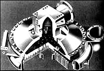
[109] Fabricated as a bell-shaped engine with tubular walls for regenerative cooling, the F-1 had an expansion area ratio of 16 to 1 (with nozzle extension) and a normal thrust of 6 670 000 newtons (1 500 000 pounds). All engines were identical except for the center engine in each Saturn V, which did not gimbal. To accomplish its mission, the F-1 relied on several subsystems, including the thrust chamber assembly (with the injector and other hardware as integral parts), the turbopump, gas generator system, propellant tank pressurization system, control system, flight instrumentation system, and electrical system. Additional paraphernalia, such as the thermal insulation blankets, were finally adopted as part of the overall F-1 engine propulsion system.30
At nearly every step of the way, the unusually large engine exhibited growing pains, and each component required special design attention in one form or another. In some cases, these problems were unanticipated; but even when designers expected a difficult development period, the solutions did not come easily. Such was the case with the F-1 injector.
The injector sprayed fuel and oxygen into the thrust chamber, introducing it in a pattern calculated to produce the most efficient combustion. To the casual observer, the final production model looked simple enough. The face of the injector, or the combustion side, contained the injection orifice pattern, determined by alternating fuel rings and oxidizer rings, both made from copper. Across the face of the injector, designers installed radial and circumferential copper baffles. These baffles extended downward and divided the injector face into a series of compartments. Along with a separate fuel igniter system, the Injector and baffles were housed in a stainless steel body.
In operation, the liquid oxygen dome, or LOX dome, located atop the thrust chamber assembly, channeled oxidizer directly into the injector. Fuel injection followed a somewhat more indirect route, entering the injector from the thrust chamber's fuel inlet manifold. As a means of ensuring the engine start and operating pressure, part of the fuel flowed directly into the thrust chamber, but the remainder was channeled by alternating tubes down the length of the regeneratively cooled thrust chamber, then back up again through the remaining tubes. The fuel entered a fuel collector manifold, consisting of 32 spokes leading to the injector. Finally, the fuel squirted through 3 700 orifices into the combustion chamber to mix with the oxidizer, which entered through 2 600 other orifices in the injector face.
Obviously, the injector demanded rigorous design work for tolerances and durability under extreme heat and pressures. At Rocketdyne,.....
[110]
![F-1 ENGINE.[link to a larger picture]](p110as.jpg)
![F-1 ENGINE SIMPLIFIED SCHEMATIC. [link to a larger picture]](p110bs.jpg)
...David E. Aldrich, the F-1 Project Manager, and Dominick Sanchini, his chief assistant, wasted little time in initiating work on the injector. "Concerning development testing, experience has shown that the injector presents the first major hurdle," Aldrich and Sanchini asserted. "Stable combustion must be attained before injector cooling and other thrust-chamber development problems can be investigated," they explained. At ....
[111]
![Engine start sequence for the S-1C stage . [link to a larger picture]](p111s.jpg)
....the outset, it might have seemed logical to scale up designs successfully developed for smaller engines. However, development of a stable injector for the 1 780 000-newton (400 000-pound) thrust E-1 engine required 18 months, and it seemed more than likely that the 4.5-million-newton (1.5-million-pound) F-1 would require something more than just a "bigger and better" design concept.
Rocketdyne's ability to run injector and thrust chamber tests with full-scale hardware in March 1959, only two months from the date of the original contract, derived from its earlier Air Force activities. Some experimental hardware was already on hand, and Rocketdyne also had a usable test stand left over from prior experiments. The first firings were made with components several steps removed from what could be expected as production models. Because the injector paced so much of the overall design and because designers and engineers wanted to start as [112] soon as possible, the thrust chamber tests used rough, heavy-duty hardware; it was cheap, and it was easy to work with.
Investigation began with a critical review of all prior operational injector work and current experimental studies to develop a promising avenue of design for the new component. Advanced theories were needed to understand the operation of an injector at much higher densities and higher chamber pressures than ever attempted. As a result of this preliminary theoretical work, the F-1 injector evolved as a construction of copper rings. This promised the necessary structural rigidity, resistance to localized hot spots, and overheating at the injector face.
With a heavy-duty component in hand, the design work progressed to the next stage of design assessment, featuring a series of water-flow and calibration tests. These procedures verified spacing and shape of injector orifices. The next step involved statistics derived from the flow and calibration tests, giving engineers the kind of data they needed to plan appropriate start sequences for the injector and engine system. The culmination of these investigations occurred in the first hot tests, "one of the most critical stages in an injector development program." These trial runs late in 1960 and early in 1961 marked Rocketdyne's first wave of troubles concerning stability of the injector at rated thrust level for duration firing.31
At the outset, planners considered three different injector designs, all of them more or less based on the H-1 injector configuration. "However, stability characteristics were notably poorer," reported Leonard Bostwick, the F-1 engine manager at MSFC. "None of the F-1 injectors exhibited dynamic stability." Once instability got started in the engine, nothing stopped it until the test engineers cut off the propellants and shutdown the entire engine. Obviously, this was not the way to successful missions. The design team tried variations of baffled injectors and flat-faced injectors with little improvement, except that the flat-faced designs could be expected to create more damage than their counterparts with baffles. Finally, all hands agreed that the attempt to scale up the H-1 injector to the F-1 size just would not work. There were too many variables: high chamber pressures, a lower contraction ratio, greater density requirements for the injector, and much larger diameter of the thrust chamber. With the concurrence of MSFC, Rocketdyne began a new path of investigation to select an injector design with inherently stable combustion characteristics.32
The snags in the F-1's progress sharpened high-level skepticism about the feasibility of an engine the F-1's size. During a meeting of the [113] President's Science Advisory Committee early in 1961, one member, Donald Hornig, reportedly expressed strong reservations about the F-1 engine program because of fundamental problems in its development, adding that it might just be too big to make it work. Hugh Dryden, NASA's Deputy Administrator, got wind of these comments and wrote to Hugh Odishaw, of the National Academy of Sciences, to help set the record straight in the scientific advisory community. Dryden reported encouraging progress on new injector designs and characterized the tribulations of the F-1 as inevitable in engine work. "Such development problems are the common experience of every engine development with which I am familiar and are nothing to be concerned about," he counseled, "so long as one makes sure that the developing agency is taking a multipronged approach to obtaining a solution."33 Several new radial injector designs now become candidates for the F-1 engine. To acquire more accurate data, engineers ran tests with scaled-down models in a special low-pressure, two-dimensional transparent thrust chamber. This permitted the use of high-speed photography and "streak movies" to analyze the performance of the injectors in simulated operation. The most promising designs graduated to full-sized models in hot-fire tests which included bomb experiments (as in the H-1) and erratic propellant flows produced by an explosively driven piston. The new designs appeared to have combustion instability, an early concern, under control until 28 June 1962, when combustion instability resulted in the total loss of an F-1 engine. From there on, as von Braun drily remarked, "This problem assumed new proportions.34
Working quickly, MSFC established a combustion stability ad hoc committee, chaired by Jerry Thomson of Marshall, with six permanent members and five consultants chosen from MSFC, Lewis Research Center, the Air Force, industry, and universities. The group got together at Huntsville on 16 July to consider the recent loss of the F-1 engine and to review Rocketdyne's R&D efforts, as well as to provide technical assistance and coordinate all research on the problem. Rocketdyne had established its own stability council by the autumn of 1962 to pursue the issue of F-1 instability and also enlisted the support of leading authorities from government and universities. Rocketdyne's group was headed by Paul Castenholz and Dan Klute, temporarily relieved of their current duties for full-time attention to combustion instability. They reported directly to William J. Brennan, Rocketdyne's chief of propulsion engineering at the time.35
Reacting to deep concern expressed within the Office of Manned Space Flight, von Braun prepared a memo in November 1962 to reassure Seamans and others at Headquarters. Von Braun emphasized Marshall's concern and praised the steps taken by Rocketdyne to deal with the situation, but promised no quick or easy solutions. The memo from von [114] Braun gave a clear insight into the frustrations in searching for answers. Although various organizations had pursued combustion-instability research for the past 10 years, nobody had yet come up with an adequate understanding of the process itself. Therefore, it had not been possible to use suitable criteria in designing injectors to void combustion instability. "Lack of suitable design criteria has forced the industry to adopt almost a completely empirical approach to injector and combustor development," von Braun said. This approach is not only "costly and time consuming," he continued, but also"..."does not add to our understanding because a solution suitable for one engine system is usually not applicable to another." Von Braun urged more extensive research on the task, and suggested that universities in particular could put Ph.D. candidates to work on aspects of combustion and combustion instability for their dissertations.36
In the meantime, two more engines were lost in tests. D. Brainerd Holmes wanted a special briefing on the problem, which he received on 31 January 1963. At the end of the presentation, Holmes commented that the goal of beating the Russians to the moon seemed to be mired in F-1 problems. He asked if it was not time to start work on a backup scheme. The briefing team, which included representatives from MSFC and Rocketdyne, convinced Holmes that new work would detract from solving F-1 difficulties, which appeared to be succumbing to intensive government-industry engineering and university research.37 In March, however, Holmes wrote to von Braun, reemphasizing the need to get the F-1 effort on schedule to avoid slips in launch dates and the lunar landing goal. "I regard this problem as one of great seriousness," Holmes wrote, and asked to be kept informed on a daily basis.38
It took 12 months for Rocketdyne to work out a baffled injector design that functioned well enough to pass the preflight rating tests. Some vexatious anomalies persisted, however, especially in the injector's inability to recover from combustion oscillations artificially induced by bombs detonated inside the thrust chamber. This situation called for added research before the F-1 could pass muster for the final flight-rated design. By July 1964, with combustion stability work continuing, Rocketdyne received an additional contract of $22 million, including miscellaneous hardware and services, with a special allocation to accelerate the company's research in combustion stability.39
Significant theoretical work was accomplished by two Princeton researchers, David Harrje and Luigi Crocco, along with Richard Priem of the Lewis Research Center. When Crocco was in Europe on sabbatical during the academic year 1963-1964, he maintained correspondence with MSFC; NASA Headquarters even approved von Braun's request to send Rocketdyne and Marshall representatives to talk with Crocco in [115] Rome.40 To investigate the phenomenon of unstable combustion, engineers and researchers employed a wide range of instrumented apparatus and other aids. Among other paraphernalia, investigators introduced high-speed instrumentation to diagnose combustion in the thrust chamber and to evaluate modifications to the original designs. The exacting attention to details led to apparently minor changes that actually proved to be of major significance. After careful calculations of the effect, enlarging the diameters of the fuel injection orifices was later judged one of the most important single contributions to improved stability. Other careful changes included readjustment of the angles at which the fuel and oxidizer impinged.41 Several techniques of rather dramatic nature were also applied in the instability research. For the layman, the most bizarre aspect of F-1 testing (like the H-1) involved the use of small bombs to upset the thrust exhaust pattern to measure the engine's ability to recover from the disturbance. By varying the size of the bombs, test engineers could create instability of different intensities and evaluate the ability of the engine to restore stable conditions.
This procedure offered an immense saving in time and costs, because it eliminated the old methods of running hundreds of engine tests in an effort to acquire a quantity of useful statistics. Moreover, the ability to artificially subject the F-1 injector to severe operational stresses eventually resulted in a superior design with excellent damping characteristics. During early tests, self-triggered instability continued for more than 1600 milliseconds-a highly dangerous condition. The successful design recovered from deliberately triggered instability in less than 100 milliseconds. The final product included the redesigned orifices for LOX and fuel to improve the distribution pattern of propellants as well as a rearrangement of the injector baffles. The baffled injector, as opposed to the flat-faced type, was particularly effective in recovery during the deliberately triggered instability tests. The minute, exacting requirements of engine development were such that these seemingly insignificant changes required some 18 months to prove out, and the flight-rated model of the F-1 injector did not receive MSFC's imprimatur until January 1965.42
In the course of F-1 engine development, Rocketdyne personnel consistently emphasized the combustion stability investigations as one of the company's stiffest challenges, and its solution as one of its most satisfying achievements. Although engineers expected difficulties in this area because big engines with high chamber pressures inevitably developed random and unpredictable combustion instability, the size of the F-1 dramatically increased the size of the challenge. Rocketdyne managed to cope with the problem, although, as Brennan admitted in an address to the American Institute of Aeronautics and Astronautics in 1967, "the [116] causes of such instability are still not completely understood."43 Even though the F-1 engine performed satisfactorily, uncertainty concerning combustion instability persisted a decade later.*
Although combustion instability and injector development became the pacing items in the F-1 program, other thrust chamber problem areas required constant troubleshooting by Marshall and Rocketdyne engineers. During the first half of 1965, MSFC monitors at Rocketdyne's production facilities in Canoga Park, California, were worried about cracks in the thrust chamber jacket, while MSFC monitors at the Edwards Air Force Base test site were frustrated by cracks in the thrust chamber tubes. Engine 014 had been in and out of the test stand more than once for injector changes and thrust chamber tube repairs. In April 1965, the MSFC monitor at Edwards reported to Huntsville that the engine was back in the test stand once more. "Engine 014 apparently has a dog of a thrust chamber," he wrote in exasperation.44 Another troubleshooting effort that required considerable attention concerned a manufacturing sequence for the injectors. Unhappily, the problem appeared after a number of engine deliveries to the Boeing Company, the contractor for the S-IC first stage of the Saturn V. The injector incorporated multiorificed copper fuel and oxidizer rings, held by steel lands (rings) installed in a stainless steel body. To attach the copper rings to the steel lands of the injector body, workers performed a brazing operation. As test runs on R&D engines accumulated more and more time, the brazed bond joint failed, with very bad separation between the copper rings and steel lands. Analysis of all prior engine deliveries disclosed similar minute failures. In a somewhat elegant solution, new procedures called for replacements using gold-plated lands to offer a superior bonding surface during brazing. During the spring and summer of 1965, this investigation involved considerable testing and metallurgical analysis, not only to pinpoint the problem, but to confirm the effectiveness of the new procedures. Finally, several engines had to be retrofitted with the new "gold-plated" injectors.45
As one group of specialists grappled with injector or thrust chamber problems, another group labored on the problem of pumping hundreds of thousands of liters of propellants out of the S-IC's propellant tanks and into the five F-1 engines. The turbopump absorbed more design effort and time for fabrication than any other component of the engine. [117] The development program began with tests of various models of turbopump evaluating the performance levels and durability of fuel and oxidizer pumps, inducers, and turbines. With a satisfactory preliminary design worked out from the model testing, workers assembled a full-sized turbopump and started tests in November 1960.46
Rocketdyne designed the turbopump as a direct-drive unit, with the oxidizer pump, fuel pump, and turbine mounted on a common shaft. During operation, the engine bearings were cooled by fuel, but this.....
![a cutaway drawing of the liquid oxygen dome and the injector plate of the F-1 engine. [link to a larger picture]](p117as.jpg) |
|
. |
|
|
|
. |
 |
[118] ....convenient feature required a special heater to keep the ball bearings from freezing up when the pump was chilled by liquid oxygen prior to engine start. The oxidizer pump, rated at 102 230 liters (24 811 gallons) per minute, supplied oxidizer to the thrust chamber as well as to the gas generator. Oxygen entered the pump through an inlet connected to the oxidizer tank by a duct, and the inlet had an inducer mounted in it to increase the pressure of the oxidizer before it reached an impeller. This sequence prevented cavitation in the liquid oxygen stream. The impeller brought the oxygen to the correct pressure, then discharged it through appropriate routes to the thrust chamber and gas generator. With a rated capacity of 57 392 liters (15 741 gallons) per minute, the fuel pump supplied the thrust chamber and gas generator in the same manner as the oxidizer pump. The fuel pump system also employed an inducer section to prevent cavitation before the fuel reached the impeller.
The turbine to drive the separate propellant pumps was an impressive piece of machinery itself-it developed 410 000 watts (55 000 brake horsepower). Designers located the turbine on the fuel-pump end of the turbopump. In this position, the units of the turbopump with the most extreme temperature differences (816°C [1 500°F] for the turbine and - 184°C [-300°F] for the oxidizer pump) were separated. Hot gases for the turbopump turbine originated in the gas generator and entered the turbine at 77 kilograms per second.47 A series of failures, 11 in all, dogged the development of the turbopumps for the F-1 engine. Two incidents were traced to structural failures of the LOX pump impeller, which called for redesign of the unit with increased strength. Explosions occurred in the other nine instances, with five during engine tests and four during component tests of the turbopump. The explosions developed from a variety of causes, such as shock loads due to high acceleration of the turbopump shaft, rubbing between critical seals and other moving parts, fatigue in the impeller section, and other problems. With some new design work and manufacturing techniques, these conditions disappeared, and investigators proceeded to cope with other problems that continued to crop up, such as the engine turbine. For the engine turbine manifold, Rocketdyne chose a new material known as René 41. This material was quite new to the manufacturers of rocket engines, and the welding process produced cracks adjacent to the weld in the heat-affected zone created by the welding pass. As a result, the company devoted considerable time and effort to ascertaining proper welding conditions and to training welders on the production lines. With the proper welding requirements finally established, Rocketdyne adopted an automatic welding procedure to complete the "fix" on this situation.48
The turbopump was a good example of the emphasis on simplicity and reliability in design philosophy. "The primary consideration in the selection of the turbopump design," MSFC managers emphasized, "was to attain reliability by using a minimum number of parts and proven [119] design concepts." Engineers were anxious to have a turbopump capable of operating at low inlet pressures, both to simplify design requirements and to have low pressure in the propellant tankage. The packaging concept of the F-1 influenced the design of the turbopump system. The main objectives in the engine configuration included designing components to be as small as possible and keeping machinery as accessible as possible. In general, the configuration of the engine package followed the pattern of the Atlas sustainer engine (the S-4), Rocketdyne's first large liquid-propellant gimbaled engine with the turbopump mounted directly on the thrust chamber. Designers located all other associated equipment on the turbopump, thrust chamber, or somewhere in between. The attraction of this approach, as in the H-1, lay in the ability to avoid flexing the high-pressure propellant ducts in concert with the gimbaling engines during a launch.
The F-1 turbopump assembly featured a variety of manufacturing techniques, heat treatment, and other processes to impart the most desirable properties to the high-performance engines. A good example of evolutionary steps in the process of engine development, these aspects of the F-1 fabrication grew out of the special materials programs associated with the H-1 engine. In both cases, designers selected materials intended to provide extra margins of safety whenever possible. For the pump's inlets, volutes, and impellers, the F-1 incorporated a lightweight, but sturdy, aluminum-alloy casting. For turbine wheels and manifold assemblies that performed under higher operating temperatures, designers favored a nickel alloy with high strength at high temperatures. After running hundreds of tests on final designs of the F-1 turbopump assembly, its developers were at last satisfied with the performance of the materials chosen and the design philosophies that were used.49
At a rate of three metric tons per second (one metric ton of RP-1 fuel and two metric tons of liquid oxygen), the F-1 was designed to burn its propellants at approximately 79 000 newtons per square centimeter (1 150 pounds per square inch) at the injector face (the high pressure was emphasized as a matter of efficient design), and within the thrust chamber convert this furious activity into a high-temperature, high- velocity gas with a yield of 4.5 million newtons (1.5 million pounds) of thrust.
Before entering the thrust chamber body tubes, RP-1 entered the fuel manifold from two diametrically opposed inlets. The bypass (which channeled about 30 percent of the fuel flow directly to the injector) reduced the power requirement for the fuel pumps-they did not have to force all the fuel down the cooling tubes and up again to the [120] combustion chamber. The remainder of the RP-1 was diverted down through 89 tubes to the nozzle exit, where a return manifold directed fuel back through the 89 return tubes. In the lower sections, the tubes were actually bifurcated units. From the fuel mainfold down to the point where the engine attained a 3.1 expansion ratio, the tubes were installed as single pieces. Below that point, the manufacturing process included two secondary fuel tubes, each spliced into the primary carrier. Designers went to this configuration to compensate for the increasing flare of the bell-shaped nozzle. The bifurcated units in the flaring nozzle permitted the engine to retain a desirable cross-sectional area in each tube and still achieve the wide, flared bell shape.50
Transforming the thrust chamber's individual tubes into a vessel capable of handling the F-1 pressure and heat required specialized metallurgical research in Rocketdyne laboratories and at MSFC. To form the regeneratively cooled engine, the F-1 was fabricated as "a tube bundle surrounded by a heavily jacketed combustion chamber, a series of bands around the nozzle, and two end rings." The basic thrust chamber included 178 primary tubes and 356 secondaries, requiring 900 meters of brazed joints between them to keep the combustion gases contained within the thrust chamber. Rocketdyne personnel expended a great deal of effort on the perfection of brazing operations required for the nickel-alloy thrust chamber assembly; it was a major challenge to perfect an alloy and a brazing technique to seal the hundreds of tubes together in a bond that would withstand high temperatures and pressures. The joints carried some of the stresses created by the expanding combustion gases, but the jacket and reinforcement bands around the tube bundle carried the primary load. This basic F-1 design reflected the features of other regeneratively cooled engines with tubular walls, such as the Atlas and H-1 engines. The greatly increased operational factors of the F-1 required more sophisticated fabrication methods, which led the company, finally, into the design and construction of the largest brazing furnace of its type in the world.
In the production of less powerful liquid-rocket tubular-walled thrust chambers, usually of pure nickel, manufacturing engineers depended on manual torch brazing with alloys of a silver-based type. With the F- 1's thrust levels up to 10 times those of prior engines, investigators knew that the old procedures needed some rethinking if the big new engine was going to hold together during a launch. For the tubes themselves, the nickel-alloy Inconel X-750 provided the high strength-to-weight ratio that was needed, but it imposed certain restraints in the brazing process. After experimentation, designers realized that technical reasons prohibited the conventional technique of torch brazing, and dictated a furnace brazing process. Then a secondary set of problems cropped up. Inconel X-750 included enough aluminum and titanium to form refractory oxides under brazing temperatures, so that "the surface of the Inconel is [121] not readily wet by most hazing alloys at elevated temperatures." Thus the brazing procedures had to begin by electrolytically depositing a thin layer of pure nickel on the tubes to eliminate the refractory oxides on the brazing surface. Despite this minor drawback in the operation, furnace brazing promised several distinct advantages over the torch method by minimizing differences in thermal stresses, combining age-hardening of the tubes with the brazing operation, and eliminating the variables of hand methods.51
With the furnace activated in 1965, furnace brazing for F-1 production proceeded in several carefully regulated sequences. After preliminary brazing operations to unite the thrust chamber tubes and other components, the scene was set for the final furnace brazing cycles to create a properly sealed thrust chamber. Inside a "clean-room" area, workers assembled the complete thrust chamber, using a special fixture devised by Rocketdyne to ensure proper alignment of the tube bundle, jacket, and end rings. In addition to the 900 meters of tube-to-tube alloy joints to be sealed inside and outside, the exterior required some 7 000 tube-to-band joints to be brazed. The brazing alloy, in a powder form, was applied by workers using hand-held spray guns, an application technique also especially developed by Rocketdyne.
Despite the highly refined and closely monitored steps leading up to the first major furnace brazing operation, this operation remained heavily laden with drama since it could almost as easily go sour as succeed. As one Rocketdyne engineer emphasized, "The furnace brazing operation represents a final step in which all the material, time, and resources expended in the fabrication of hundreds of thrust chamber parts and subassemblies are committed. In many respects it is similar to the launch of the vehicle itself, since failure of any one of the numerous controls exercised during the furnace brazing operation could result in a poorly brazed, unacceptable piece of hardware." No wonder, then, that Rocketdyne expended so much attention on the furnace, which incorporated several unique features of design and performance.52
The F-1 design included a thrust chamber extension, or "nozzle skirt." As engineers pondered the design of the F-1 and the problem of disposing of the turbine exhaust, the idea of the nozzle skirt promised several design advantages. A circumferential exhaust manifold collected the turbine exhaust gases and directed them through the nozzle skirt into the engine's exhaust plume. The skirt was designed with double walls, and numerous slots in the wall allowed the gases to exit with the jet stream of the exhaust. The effect was to introduce a cooler boundary layer to protect the walls of the thrust chamber extension. With the.....
[122]
![A cutaway drawing of the F-1 thrust chamber. [link to a larger picture]](p122as.jpg) |
.
|
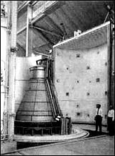 |
|
. |
| |
|
|
|
....disposal of the turbine exhaust gases into the thrust chamber by way of the nozzle extension, Rocketdyne designers realized the advantages of a neat, comparatively lightweight system. There was no need for extra attachments such as a turbine exhaust duct, and the extension favorably increased the expansion ratio. Designed with simple bolted attachments, the extension could be conveniently removed for shipping and handling of engines and stage. The simplicity of the design allowed the engine to be easily test-fired following reattachment of the nozzle skirt at the test site.
To help keep the S-IC propellant tanks under pressure, the engine contractor supplied elements of the propellant tank pressurization system. The key to the system was the heat exchanger, which heated gaseous oxygen and helium to pressurize the oxidizer tank and fuel tank, respectively. Using the vehicle's own oxidizer as part of the propellant tank pressurization system illustrated harmoniously integrated design of many of the rocket systems and subsystems. Another good example involved the use of the fuel as the fluid medium in the hydraulic control system. The hydraulic design itself constituted a notable design advancement for an engine the size of the F-1. The system cut out many sets of [123] previously required pneumatic controls and electrical components and automatically increased reliability. Once the fuel used as the hydraulic fluid had performed its programmed chores in engine components, a myriad of tubing routed it back to the turbopump fuel inlet fur combustion in the thrust chamber.
The frustrations of perfecting an engine the size of the F-1 ran the gamut from internal hardware to external accessories. The high operating temperatures of the engine called for varied insulation at many points, and the super-hot blasts from the clustered engines created the need for special insulation to protect the engines from their own exhaust. During the vehicle's ascent, the plumes from the five F-1 engines expanded with decreasing ambient pressure until they become one searing, gargantuan sheet of flame, and a backlash stream of hot gases played over all the exterior surfaces of the engines. For this reason, designers had to protect the engines from thermal attack during the flight, as well as consider the high heat radiation encountered as the engines built up to mainstage thrust levels at liftoff. Thus, the F-1 engine acquired its distinctive external insulation "cocoon," molded into segments and attached to the engine with brackets. Despite its deceptively simple appearance, the development of this insulation cocoon also experienced its share of problems in attachment and weight.
Engineers employed a direct and brutal method to test the engine insulation cocoon installed on the F-1. Workers placed an engine, enclosed in its protective wraps, inside a special wind tunnel. At one end, they installed a J-57 jet engine, complete with an afterburner, and positioned it to aim the devastating jet exhaust directly at the insulated F-1. With added quilting, thicker inner skin, and improvements in stressed areas, the engine insulation received qualification for flight. Only one month hitch occurred. In the humid, semitropical environment of Cape Kennedy, the internal quilting acted like a sponge and became thoroughly saturated during a stiff thundershower. While a Saturn V waited on the pad, engineers ran frantic tests with water-soaked insulation panels under simulated flight conditions. These tests introduced the final modifications to the insulated cocoons-strategically placed vents to let off steam from the moisture-laden internal quilting.53
From the beginning, the most complete facilities for full-scale F-1 testing existed at Edwards Air Force Base, where Air Force work on the engine first began. Their facilities included several engine test stands and a thrust chamber stand, also used for injector design studies. The first engine tests using prototype hardware occurred in the test stand originally built for the Atlas program and converted to take the larger F-1 [124] dimensions. Researchers scheduled advanced engine work to use a new stand, capable of holding a pair of engines side by side. It scat a towering complex, equivalent to an 11-story building, built with heavily reinforced concrete base and a steel girder framework anchored deeply in the desert granite to withstand the punishment of the F-1 engines at full throttle. At the peak of the development program, Rocketdyne used five separate engine stands at the Rocket Engine Test Site, an integral unit of the Edwards Air Force Base complex. The equipment at the Edwards Rocket Engine Test Site also included a component test stand, a dual-position facility used for chamber and injector work at full thrust levels. Technicians began some of the first preliminary design work on this stand, even though it was not feasible at the time to build supply tanks to deliver propellants for more than a 20-second run. Despite the short duration of the experiments, the 20 seconds of roaring engine operation called for some equipment of remarkable proportions. Workmen put together the high-pressure propellant tanks with stainless steel plates 13 centimeters thick and installed fuel and oxidizer control valves that weighed 6 metric tons each. With such a complement of metal, the "battleship test" stand was aptly named.54
To accelerate the test schedules for production models of the F-1, executives at MSFC decided to test the engines in Huntsville and ordered appropriate modifications to the west side of MSFC's static test tower. Thus, while the engine test stands at Edwards supported ongoing research and development, Marshall personnel checked out the first batch of production engines during 1963, sending the F-1's thundering roar through the Tennessee River valley. The tempo of F-1 engine tests picked up during 1964, as MSFC personnel ran numerous static tests in Huntsville, and Rocketdyne supervised continuing work at Edwards Air Force Base. In October, the new dual-position test stand at Edwards became operational. The Director of MSFC, Wernher von Braun, flew out to California for the ceremonies, where he accepted the newly activated stand on behalf of NASA and then assigned operational responsibility to Rocketdyne. With all test stands utilized at full capacity, the Flight Rating Tests of the F-1 propulsion system soon concluded, and flight qualification was verified by NASA spokesman by the last month of the year. The concurrent lines of development of stages and engines now began to converge in Huntsville where a "live" test stage (the S-IC-T), with a full complement of five F-1 engines, awaited its first dramatic test firing. The use of MSFC facilities on 16 April 1965 put this phase of testing two months ahead of schedule, and the 6.5-second ignition of the S-IC-T stage generated 33 000 000 newtons (7 500 000 pounds) of thrust, more collective rocket power than ever before achieved.
During 1966, the last year before the F-1 and J-2 powered Saturn V was scheduled for its first unmanned launch, the F-1 passed NASA's first article configuration inspection, the first major Apollo-Saturn propulsion.....
[125]
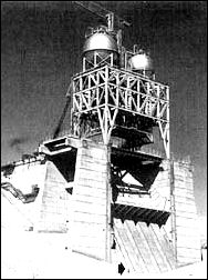
....system to Pass this exam, and on 6 September the F-1 received complete qualification for manned missions. The final tests for MSFC occurred on 15 November, with the acceptance firing of the S-IC-3 first stage: subsequent acceptance firings were earmarked for the Mississippi Test Facility near the Gulf, a more convenient location in terms of logistics between the test site and launch facilities at KSC. Before the epochal voyage of Apollo 11 began on 16 July 1969, five Saturn V launch vehicles lifted off from Cape Kennedy: one in 1967; two in 1968; and two more in early 1969. Despite the thousands of metric tons of cryogenic materials already consumed in research and in the hundreds upon hundreds of tests already accomplished, the pace of research involving the F-1 only seemed to quicken in the concluding months before Apollo 11 began its flight. Dozens of additional tests of the complete engine were run at Huntsville and at Edwards, as contractors and NASA engineers determinedly verified the maturity and reliability of the mammoth rocket engine.55
The H-1 and F-1 engines, as well as other engines in the Saturn series of vehicles, achieved remarkable records in operational reliability and longevity during the Apollo program. Both the H-1 and F-1 demonstrated consistent performance characteristics during flight missions, a credit to all the government and contractor personnel who.....
[126]
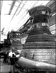
.....contributed to their success. When the Saturn V took the central role in the late 1960s and early 1970s, the remaining nine Saturn S-IB first stages, along with their 72 H-1 engines, went into storage. When they were earmarked for use in the Skylab program, many people wondered if such old equipment would still be reliable.
In the spring of 1971, nine years after the delivery of the last production unit, technicians pulled one of the H-1 engines out of hibernation, to test the "certified lifetime" of seals, gaskets, and other components. The test was important, not only for the immediate purpose of Skylab, but to know how other liquid-fueled rocket engines stored away for future missions were faring. After an extensive pretest examination, the H-1 was installed in a test stand at MSFC. Engineers put the engine through its paces: three separate starts, followed by a full-duration run of 140 seconds. The engine performed as well as at its qualification test firing, 108 months earlier. MSFC personnel tore the engine down after firing to see if they could discover any weaknesses, but all the seals and other critical parts were still in good shape and fully serviceable. Marshall officials sent the engine back into storage, satisfied that they could all be called upon to serve any time within yet another 8-10 years. A year later, during June 1972, Rocketdyne personnel did similar tests on an F-1 engine that had been delivered to MSFC in 1965, tested in 1966, and put into storage. The engine was run through two extended duration firings at Edwards Air Force Base, then subjected to rigorous inspection and analysis. The engine showed no abnormalities.56 Faith in the engines' lifetime was justified by the successful launch of the Orbital [127] Workshop aboard a two-stage Saturn V (S-IC first stage and S-II second stage), followed by the three successful manned launches of the Saturn IB in support of the Skylab program in 1973, followed by another Saturn IB in the Apollo-Soyuz Test Project in 1975 (see chapter 13).
To appreciate the efficiency and dependability of the H-1, the contributions of engine technology from the Thor, Jupiter, and Atlas programs must be remembered. These missile propulsion systems contributed handsomely to the H-1 engine's thrust chamber, turbopump assembly, gas generator system, control valves, and other engine assemblies. But the H-1 emerged from its R&D gestation period as a separate and distinct engine system. Its components had been completely repackaged for compactness and improved accessibility-the latter a special problem for the H-1, created by the first-stage "boat tail." Various components were refined and strengthened for higher pressures, temperatures, and propellant flow to achieve the higher thrust levels demanded for the Saturn missions. Altogether, the designers contrived an assembly that was smaller and lighter in comparison to its enhanced performance.57
Although the F-1 had its roots in early Air Force studies, it was a "newer" engine than the H-1. Troubles with the F-1, however, were primarily a function of proportions, not innovations. Both engines used the same liquid oxygen and RP-1 propellants, but size and performance characteristics made the
F-1 fundamentally different. The H-1 experienced R&D Problems as it was uprated in thrust. Taking proven H-1 components, such as the injector, and scaling them up to F-1 requirements turned out to be not only difficult but basically impossible. The job necessitated a fresh approach. Reworking the engine and the injector to cope with combustion instability entailed an R&D effort of notable scope, embracing scientific and technical specialists from MSFC and other NASA centers, the contractor, other government agencies, private industry, and universities. In addition to other F-1 complications, the nature of the facilities for testing and manufacturing (furnace brazing, for example) of the F-1 also differentiated it from the smaller H-1.
The extent to which cryogenic oxidizers and fuels of the RP-1 type had been used in earlier engines made the H-1 and F-1 conventional propulsion systems. Other Saturn cryogenic engines used a different, more potent fuel: liquid hydrogen. As the first large rocket engines to use a cyrogenic fuel, the RL-10 and J-2 were unconventional.
* In a note to the
author (8 July 1976), John Sloop, a senior NASA propulsion engineer,
noted that combustion instability, like engine knock, has long been
studied, and engineers had learned to deal with it. But neither was
yet fully comprehended.